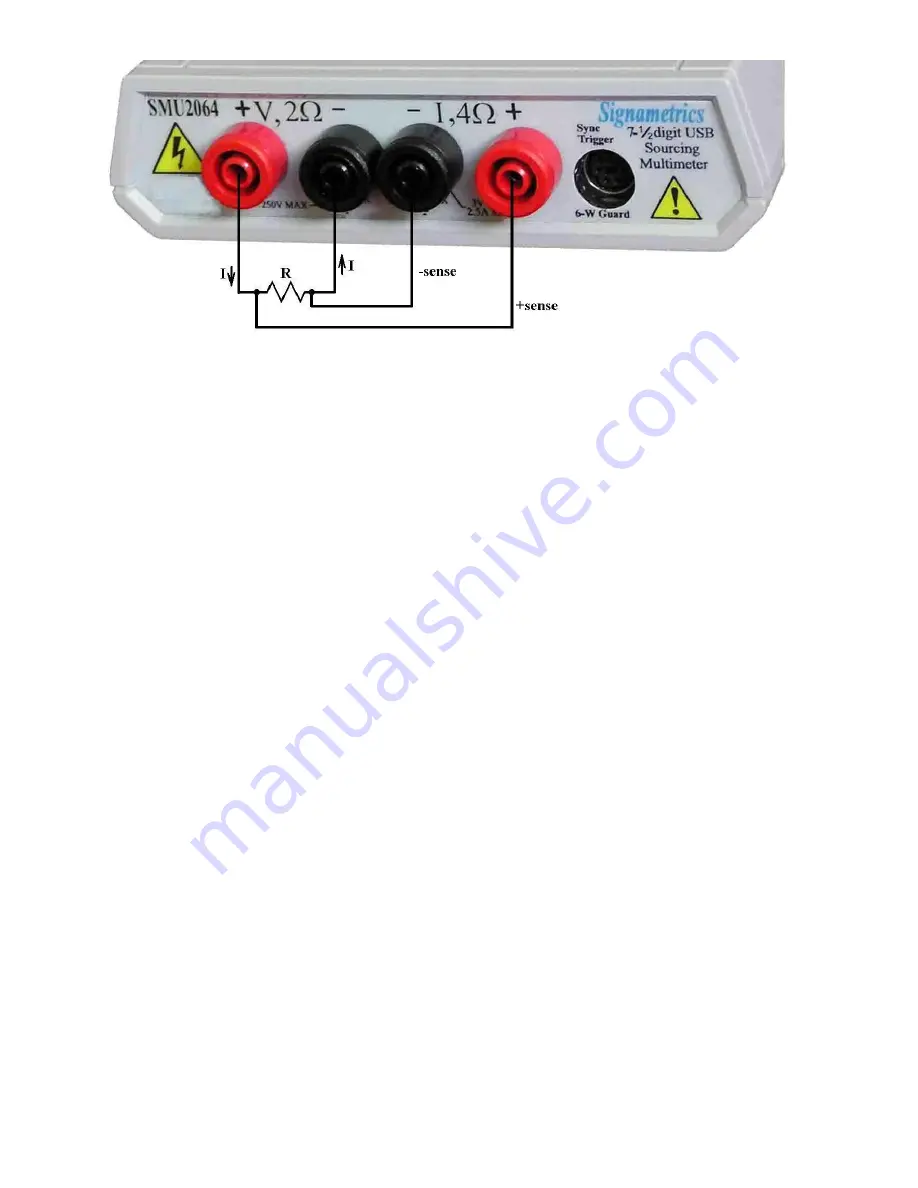
Figure 4-1. The
I,4
-
and
I,4
+
sense leads should be closest to the body of the resistor when making
4W
measurements. Mind the lead resistance of the
V,2
+
and
V,2
-
lines.
4.3.3 Using Offset Ohms function (SMU2064)
There are many cases where the resistance bening measured has a series voltage. This can be while using
multiplexers with high Thermo-Voltaic voltage (due to poor relays). These errors are also associated iwht
measuring devices that by design have a series voltage such as Peltier devices, thermocouples etc.. The
presence of these voltages can cause significant measurement error. These errors effect both 2-Wire and
4-Wire measurements. Engaging the Offset Ohms mode reduces most of this error at the cost of slower
measurement speeds. Note that with this function, the internal resistance of low voltage sources such as
batteries can be measured. This function is disabled by default. The
DMMSetOffsetOhms()
function
controls the operation of the Offset Ohms mode. To enable it, enter TRUE (1). The result is an effective
measurement rate that is approximately twice as slow. To disable this function enter FALSE (0).
Both negative and positive offset voltages can be corrected for. There are some limits however. For one,
the absolute value of the offset voltage,
Vo
, must be smaller than 230mV for the 24
and 240
ranges,
and smaller than 2.3V for all other ranges. Also, the value of
I*R + Vo
must be smaller than 220mV for
the 24
and 240
ranges and 2.2V for other ranges.
I
is the resistance test current (see sectin 2.3) and
R
is the resistance being measured.
Example: Measuring a 20k
resistor using the 24k range, provides test current,
I
= 100µA (section 2.3).
Therefore the maximum positive offset voltage
Vo
= 2.2V – (100 µA * 20k) =
+200mV
. The maximum
negative voltage
Vo
= -2.2V - (100 µA * 20k) = -4.2V, however, since the limit on
Vo
is -2.3V, (see
section 2.3.5), the most negative value of
Vo
is only
-2.3V
.
With aperture times lower than 5ms, an increasing error will be observed. It is therefore recommended to
use this function in conjunction with apertures greater than 5ms.
4.3.4 6-wire Guarded Resistance Measurement (SMU2064)
The 6-Wire Guarded resistance measurement provides means to make resistance measurements in-
circuite, or where the resistor being measured is connected to other circuite elemens which are loading it.
DMMs not capable of Guarding will exhibit very large errors in this type of measurement, where the
2060 isolates the resistor-under-test by maintaining a guard voltage at a user-defined node. The guard
voltage prevents the shunting of the DMM test current from the resistor-under-test to other components.
The Guard Source and Guard Sense terminals are provided at pins 1 and 6 of the DIN connector
respectively.
Warning! The DIN connector pins are only protected to a maximum of 35 V with respect to the PC
chassis or any other DMM terminal. Do not apply any voltages greater than 35 V to the DIN
Signametrics
38
Содержание SMU2060
Страница 26: ...Signametrics 26 PXI Instrumentation Switching modules SMX4030 SMX4032 IVI COM driver...
Страница 81: ...81 Signametrics Postive Value 100 Warning code Example char cBuf 64 int status status DMMGetCalDate 0 cBuf...
Страница 106: ...Signametrics 106 Postive Value 100 Warning code Example char cBuf 64 int status status DMMPeriodStr 0 cBuf...


