background image

SIGLENT


10    SDM3055


Quick Start


5. 2-Wire Resistance Measurement 

Connect  the  test  leads  and  tested  circuit  as  the  following 

diagram, red test lead to the HI Terminal and black lead to 

the LO Terminal.


6. 4-Wire Resistance Measurement 

Connect  the  test  leads  and  tested  circuit  as  the  following 

diagram, red test lead to the HI Terminal and black lead to 

the LO Terminal.


Содержание SDM3055A

Страница 1: ...User Manual SDM3055 Digital Multimeter UM06035 E02A 2014 SIGLENT TECHNOLOGIES CO LTD ...

Страница 2: ... Statement SIGLENT products are protected by patent laws in and outside of the P R China SIGLENT reserves the rights to change the specification and price Information in this publication replaces all previous corresponding published material Contents in this manual are not allowed to be copied extracted or translated in any form or by any means without SIGLENT s permission ...

Страница 3: ...e to a high voltage Observe all terminal ratings Please observe all ratings and sign instructions on the instrument to avoid fire or electric shock Before connecting the instrument please read the manual carefully to gain more information about the ratings Do not operate with suspected failures If you suspect that the product is damaged please contact SIGLENT s qualified service personnel to inspe...

Страница 4: ... 1 2013 Input terminal protection limitation Protection limitation is defined for the input terminal 1 Main input HI and LO terminal HI and LO terminals are used for Voltage Resistance Capacitance Continuity Frequency and Diode measurement Two protection limitations are defined HI LO protection limitation 1000VDC or 750AVC It s the maximum measurable voltage The limitation can be expressed as 1000...

Страница 5: ...rement Category II includes electrical devices connected to mains at an outlet on a branch circuit such as most small appliances test equipments and other devices that plug into a branch outlet or socket SDM3055 is capable of making measurements with the HI and LO inputs connected to mains in such devices up to 600VAC or the branch outlet itself However the HI and LO terminals of SDM3055 can t be ...

Страница 6: ...sed on the instrument Symbols may appear on the instrument WARNING Warning statements indicate the conditions and behaviors that could result in injury or loss of life CAUTION Caution statements indicate the conditions and behaviors that could result in damage to this product or other properties CAT I 1000V IEC Measurement Category I The highest measurable voltage is 1000Vpk in the HI LO terminal ...

Страница 7: ...ch can meet users demand furthest Main Features 4 3 inch color TFT LCD display screen with 480 272 high resolutions Real 5 digits readings resolution Up to 150rdgs S measurement speed True RMS AC Voltage and AC Current measurements 1 Gb Nand Flash size mass storage configuration files and data files Built in cold terminal compensation for thermocouple Support standard SCPI and control software on ...

Страница 8: ...and Operation Introduce the functions and operations of SDM3055 in details Chapter 3 Application Examples Introduce you how to use strong measurement functions of this instrument easily through some examples Chapter 4 Measurement Tutorial Guide you to eliminate the errors that may appear during your measurement and obtain accurate result Chapter 5 General Troubleshooting Provide you some general t...

Страница 9: ... Select Measurement Speed 11 Basic Measurement Functions 12 To Measure DC Voltage 13 To Measure DC Current 15 To Measure AC Voltage 17 To Measure AC Current 19 To Measure 2 Wire 4 Wire Resistance 21 To Measure Capacitance 25 To Measure Frequency or Period 27 To Test Continuity 31 To Test Diode 33 To Measure Temperature 35 Measurement Parameters 38 AC Filter 38 DC Input Impedance 39 Short circuit R...

Страница 10: ...urement 83 Example 4 dB Measurement 84 Example 5 Limits Test 86 Example 6 Thermocouple setting and measurement 88 Example 7 To Use Hold Measurement Function 90 Example 8 To Use Application Software EasySDM 92 Chapter 4 Measurement Tutorial 93 True RMS AC Measurement 93 Crest Factor Errors non sinusoidal inputs 94 Loading Errors AC Voltage 95 Application of the Analog Filter 96 Chapter 5 General Tr...

Страница 11: ...SIGLENT SDM3055 Digital Multimeter 1 Chapter 1 Quick Start General Inspection Handle Adjustment The Front Panel The Back Panel To Connect Power Line User Interface To Use Safety Lock ...

Страница 12: ...strument caused by the shipment will be compensated by the shipper or carrier SIGLENT will not be responsible for the free repair or replacement 2 Inspect the instrument If there exit any mechanical damages or lacking of components or the instrument fails the electrical and mechanical test please contact your SIGLENT sales 3 Check the accessories Check the accessories according to the packing list...

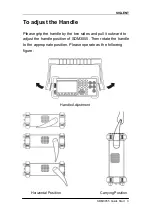
Страница 13: ...instrument stably so that users can manipulate and observe the display better Please grip the handle by the two sides and pull it outward Then rotate the handle to the appropriate position Please operate as the following diagram Diagram 1 1 Handle adjustment Diagram 1 2 Horizontal Position Diagram 1 3 Carrying Position ...

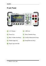
Страница 14: ... control buttons are group by logic and users only need choose corresponding buttons to carry out basic operations as shown in Diagram 1 4 Diagram 1 4 Front Panel Overview LCD Display USB Host Power Key Menu Keys Basic Measurement Function Keys Auxiliary Measurement Function Keys Enable Trig Keys Direction Keys Signal Input Port ...

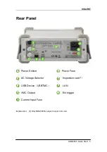
Страница 15: ...N and GPIB Only for SDM3055A as shown in the following diagram Diagram 1 5 Back Panel Overview Power Socket Power Fuse AC Voltage Selector Inspection card interface USB Device USBTMC 10 100 Ethernet VMC Output Ext Trig Current Input Fuse NOTE SDM3055 doesn t support GPIB and Inspection Card SDM3055A doesn t support Inspection Card SDM3055S doesn t support GPIB ...

Страница 16: ...110 100 120V 45 440Hz AC or 220 200 240V 50 60Hz AC in accordance with power standards in your country 2 Connect the instrument to AC supply via power cord supplied by SIGLENT 3 The power indicator light on the front panel will glitter slowly 4 Press the power key on the front panel the instrument will be started a few seconds later ...

Страница 17: ...ser Interface Single Display Diagram 1 6 Single Display Interface Dual Display Diagram 1 7 User Interface Main Display Function Reading Display Measurement Range Trigger Mode Unit Softkey Menu Vice display Main Display Function Main Display ...

Страница 18: ...esistance To Measure Frequency Capacitance To Test Continuity Diode To Measure Temperature Optional Multiple Scan Card To use Dual display Function or Set Up the Utility Acquire Function or Help System Math Function or Display Function Run Stop Single Trigger Hold Measurement Function To Switch Functions or Return to Local Menu To Select Measurement Range ...

Страница 19: ...f the front panel as the following diagram To increase range To decrease range Diagram 2 1 Range Selection Keys Method 1 By Function keys on the Front Panel Auto Range Press to switch between Auto Range and Manual Range Manual Range Press to increase range and press to decrease range Method 2 By softkeys on the measurement main interface as Diagram 2 2 Auto Range Press Auto to choose Auto Range me...

Страница 20: ... so as to protect the instrument against damage and get exact data as much as possible when it s hard to predict the range of measurement 4 For Dual display Function the measurement ranges of Main display and vice display are similar and can t be changed independently 5 The range is fixed during testing the Continuity and Diode The range of continuity is selected as 2kΩ while the Diode is 2V 6 Aut...

Страница 21: ... DCI ACI and 2 Wire 4 Wire Resistance Slow Middle and Fast 2 There is a linkage for both reading resolution and reading measurement rate 3 5 reading s belongs to 5 5 digit resolution 4 Both 20 reading s and 123 reading s belong to 4 5 digit resolution 5 The reading resolution of Temperature is fixed at 5 5 digit and Slow respectively 6 The reading resolutions and measurement rates of both Diode an...

Страница 22: ...gital Multimeters have following basic functions To Measure DC Voltage To Measure AC Voltage To Measure DC Current To Measure AC Current To Measure 2 4 Wire Resistance To Measure Capacitance To Test Continuity To Test Diode To Measure Frequency or Period To Measure Temperature ...

Страница 23: ...lowing steps NOTE DC Voltage is always the selected function when the Multimeter is turned on Operating Steps 1 Press on the front panel to enter the DC Voltage measurement interface as shown in Diagram 2 4 Diagram 2 4 DC Voltage Measurement Interface 2 Connect the red lead to terminal Input HI and black lead to terminal Input LO as the following diagram Diagram 2 5 Sketch Map for Measuring DC Vol...

Страница 24: ...t the DC resistance as 10M default value or 10G Users can execute DC voltage measurement directly without modifying this parameter which has been setup before leaving factory 5 Set AC Filter function Press Filter to open or close the AC Filter NOTE Only DC Voltage and DC Current have this function 6 Set relative value Optional operation Press Rel to open or close Relative math function When it is ...

Страница 25: ...ll be introduced in details as the following steps Operating Steps 1 Press and on the front panel to enter the DC Current measurement interface as shown in Diagram 2 6 Diagram 2 6 DC Voltage Measurement Interface 2 Connect the red lead to terminal Input I and black lead to terminal Input LO as the following diagram Diagram 2 7 Sketch Map for Measuring DC Current ...

Страница 26: ...4 Set AC Filter function Press Filter to open or close the AC Filter 5 Set relative value Optional operation Press Rel to open or close Relative math function When it is opened the reading displayed is a relative value which comes from the result of actual measurement value subtracts the value that has been set Please refer to Math Functions in Chapter 2 to know about the details 6 Read measuremen...

Страница 27: ...will be introduced in details as the following steps Operating Steps 1 Press on the front panel to enter the AC Voltage measurement interface as shown in Diagram 2 8 Diagram 2 8 AC Voltage Measurement Interface 2 Connect the red lead to terminal Input HI and black lead to terminal Input LO as the following diagram Diagram 2 9 Sketch Map for Measuring AC Voltage ...

Страница 28: ...input protection exists in every range 4 Set relative value Optional operation Press Rel to open or close Relative math function When it is opened the reading displayed is a relative value which comes from the result of actual measurement value subtracts the value that has been set Please refer to Math Functions in Chapter 2 to know about the details 5 Read measurement result Select required measu...

Страница 29: ... be introduced in details as the following steps Operating Steps 1 Press and on the front panel to enter the AC Current measurement interface as shown in Diagram 2 11 Diagram 2 11 AC Voltage Measurement Interface 2 Connect the red lead to terminal Input I and black lead to terminal Input LO as the following diagram Diagram 2 12 Sketch Map for Measuring AC Current ...

Страница 30: ... are available for setting every range 4 Set relative value Optional operation Press Rel to open or close Relative math function When it is opened the reading displayed is a relative value which comes from the result of actual measurement value subtracts the value that has been set Please refer to Math Functions in Chapter 2 to know about the details 5 Read measurement result Select required measu...

Страница 31: ...istance will be introduced in details separately 2 Wire Resistance Operating Steps 1 Press on the front panel to enter the 2 Wire Resistance measurement interface as shown in Diagram 2 13 Diagram 2 13 2 Wire Resistance Measurement Interface 2 Connect the red lead to terminal Input HI and black lead to terminal Input LO as the following diagram Diagram 2 14 Sketch Map for Measuring 2 Wire Resistanc...

Страница 32: ...ation Press Rel to open or close Relative math function When it is opened the reading displayed is a relative value which comes from the result of actual measurement value subtracts the value that has been set Please refer to Math Functions in Chapter 2 to know about the details 5 Read measurement result Select required measurement rate reading rate by pressing Speed and read the measurement resul...

Страница 33: ... panel to enter the 4 Wire Resistance measurement interface as shown in Diagram 2 14 Diagram 2 15 4 Wire Resistance Measurement Interface 2 Connect the red lead to terminal Input HI and black lead to terminal Input LO as the following diagram Diagram 2 16 Sketch Map for Measuring 4 Wire Resistance ...

Страница 34: ...ptional operation Press Rel to open or close Relative math function When it is open the reading displayed is a relative value which comes from the result of actual measurement value subtracts the value that has been set Please refer to Math Functions in Chapter 2 to know about the details 5 Read measurement result Select required measurement rate reading rate by pressing Speed and read the measure...

Страница 35: ...ill be introduced in details as the following steps Operating Steps 1 Press on the front panel to enter the Capacitance measurement interface as shown in Diagram 2 16 Diagram 2 17 Capacitance Measurement Interface 2 Connect the red lead to terminal Input HI and black lead to terminal Input LO as the following diagram Diagram 2 18 Sketch Map for Measuring Capacitance ...

Страница 36: ...el to open or close Relative math function When it is opened the reading displayed is a relative value which comes from the result of actual measurement value subtracts the value that has been set Please refer to Math Functions in Chapter 2 to know about the details 5 Read measurement result Capacitance measurement is fixed at Slow rate Therefore you can t adjust the reading rate when reading the ...

Страница 37: ...equency or Period will be introduced in details as the following steps To Measure Frequency Operating Steps 1 Press and on the front panel to enter the Frequency measurement interface The lower right corner of the screen shows the unit of Frequency as shown in Diagram 2 17 Diagram 2 19 Frequency Measurement Interface 2 Connect the red lead to terminal Input HI and black lead to terminal Input LO a...

Страница 38: ...ess Rel to open or close Relative math function When it is opened the reading displayed is a relative value which comes from the result of actual measurement value subtracts the value that has been set Please refer to Math Functions in Chapter 2 to know about the details 5 Read measurement result Frequency measurement is fixed at Slow rate Therefore you can t adjust the reading rate while reading ...

Страница 39: ...gram 2 21 Diagram 2 21 Period Measurement Interface 2 Connect the red lead to terminal Input HI and black lead to terminal Input LO as the following diagram Diagram 2 22 Sketch Map for Measuring Period 3 Choose a proper voltage range according to the measured circuit Table 2 9 Measurement Characteristics of Period Ranges 200mV 2V 20V 200V 750V Measurement Range 20Hz 1MHz Input Protection 750Vrms o...

Страница 40: ...rom the result of actual measurement value subtracts the value that has been set Please refer to Math Functions in Chapter 2 to know about the details 5 Read measurement result Period measurement is fixed at Slow rate Therefore you can t adjust the reading rate while reading the result 6 View history data There are four types of way to view historical data Number Bar Meter Trend Chart and Histogra...

Страница 41: ...one it is considered being connected with instrument The method to test Continuity will be introduced in details as the following steps Operating Steps 1 Press on the front panel to enter the Continuity test interface as shown in Diagram 2 23 Diagram 2 23 Continuity Measurement Interface 2 Connect the red lead to terminal Input HI and black lead to terminal Input LO as the following diagram Diagra...

Страница 42: ...A Ranges Fixed at 2kΩ Open circuit Voltage 8V Input Protection 1000V on all ranges HI terminal Beep Condition 0 Rtesting Short circuit impedance 1Ω Short circuit impedance 2kΩ 4 Set the Beeper function Press Beeper to turn on or off the Beeper If the circuit is continuous the instrument will beep once when the Beeper is turned on 5 Search for the test point and read measurement result NOTE Before ...

Страница 43: ...od to test Diode will be introduced in details as the following steps Operating Steps 1 Press and on the front panel to enter the Diode test interface as shown in Diagram 2 25 Diagram 2 25 Diode Test Interface 2 Connect red lead to both terminal Input HI and anode of the Diode and black lead to both terminal Input LO and cathode of the Diode as the following diagram Diagram 2 26 Sketch Map for tes...

Страница 44: ...erse the probes and measure the voltage in the diode once more Evaluate the diode according to the following rules If the Multimeter shows overload when in reverse bias model it indicates that the diode is normal If the Multimeter shows voltage about 0V and the instrument beeps persistently when in forward and reverse bias model it indicates that the diode is short If the Multimeter shows overload...

Страница 45: ...erating Steps 1 Press on the front panel to enter the Temperature measurement interface as shown in Diagram 2 27 Diagram 2 27 Temperature Measurement Interface 2 Connect the red lead to terminal Input HI and black lead to terminal Input LO as the following diagram Diagram 2 28 Sketch Map for Measuring Temperature 3 Press Load and use direction keys to select the required file Then press Read to re...

Страница 46: ...ine to view the configuration as shown in the following diagram Diagram 2 30 Configuration of the Sensor 5 Press Display to choose a display mode The Multimeter supports three display modes Temperature Value Measured Value and All Diagram 2 31 Choose Display Mode of Temperature Measurement ...

Страница 47: ...Temperature And Voltage Values 6 Press Units to choose the unit of temperature The Multimeter supports three units C F K Diagram 2 33 Unit Selection Interface 7 Set relative value Optional operation Press Rel to open or close Relative math function When it is opened the reading displayed is a relative value which comes from the result of actual measurement value subtracts the value that has been s...

Страница 48: ...them to meet your own requirements AC Filter AC Filter is applicable for DC Voltage and DC Current measurement When DC Voltage or DC Current function is selected press Filter to open the filter as shown in the following diagram If AC component existing in inputted DC signal it can be filtered by AC Filter so as to make the data more exactly Diagram 2 34 Turn on or off AC Filter ...

Страница 49: ...e is general for the Multimeter but for 200mV and 2V manual ranges 10GΩ should be chosen for better result The current selection will be saved in nonvolatile memory DC input impedance selection While the DC input impedance is selected as 10MΩ the input impedance of all measurement range is 10MΩ While the DC input impedance is selected to 10GΩ the input impedance for 200mV and 2V measurement range ...

Страница 50: ... to enter interface as the following diagram Diagram 2 36 Set Up the Short circuit Resistance 2 Use direction keys to change the parameter values Press left and right directional keys to choose different digits Each press for the Left key former number will be selected vice versa Press up and down keys to change the current digit value Each press for the up key value will be increased 1 vice versa...

Страница 51: ...tion Combinations shade is available Main Display Function DCV DCI ACV ACI FREQ PERIOD 2 Wire R 4 Wire R Cap Vice Display Function DCV DCI ACV ACI FREQ PERIOD 2 Wire R 4 Wire R Cap Explanations 1 If the same measurement function is used in both Main and Vice Display The readings in both of the display will update at the same time If math function dBm dB is used in Main Display when opening Vice Di...

Страница 52: ...Statistics Limits Relative is used in Main Display when opening Vice Display the result will still be shown in Main Display and Vice Display will show the second selected function normally 3 If Temperature function is used in Main Display set the display mode Display All Then the result corresponding value will be shown in Main Display and the current measurement value is shown in Vice Display 4 A...

Страница 53: ...on as the following diagram shows Diagram 2 37 Utility Function Configuration Interface Table 2 13 Utility Function Menu Description Function Menu Description Store Recall Store or recall setting files Manage File Create a new file copy rename or delete a file I O Config Set up LAN and GPIB parameters Test Admin Provide board test and firmware update function System Setup Set up system information...

Страница 54: ...meters and data files in the local storage as well as in USB storage Operating Steps 1 After entering into the function menu of Utility press Store Recall to enter the interface as shown in diagram 2 38 Diagram 2 38 Store and Recall Interface 2 Press Store Settings to enter the following interface Diagram 2 39 Store Settings Interface ...

Страница 55: ...to enter the following interface Use direction keys to choose storage path and location and press Select to recall the corresponding file Diagram 2 40 Recall Function Interface 4 Press Power on to set the Power On state of the instrument You can choose Last or Factory Default as the initial state when the instrument is turned on The configuration is effective when you restart the Multimeter DC Vol...

Страница 56: ... as well as in USB storage Operating Steps 1 After entering into the function menu of Utility press Manage File to enter the interface as shown in diagram 2 41 Diagram 2 41 Manage File Interface 2 Choose the file location Press Browse and use direction keys to select the corresponding file 3 Press File Name to enter the following interface Diagram 2 42 Input File Name ...

Страница 57: ... Press Done to save the current file and return to the higher level menu Press Cancel to cancel the current operation and return to the higher level menu 4 Press Action and select Folder Capture Display Copy Rename or Delete to do the corresponding operation Table 2 15 Action Settings Function Menu Description Folder Press Create Folder to create a new folder Capture Display Press Save Screen to s...

Страница 58: ...N Settings The Multimeter enables users to operate instrument remotely by LAN interface and store or recall internet settings You can look over current LAN settings and set up IP address and subnet mask After entering into the function menu of Utility press I O Config Select On LAN Settings Modify Settings to enter the following interface Diagram 2 44 LAN Settings Interface ...

Страница 59: ... Settings Only for SDM3055A Each device on the GPIB IEEE 488 interface must have a unique address The default address is 30 when the instrument is leaving the factory The address of Multimeter can be any integral value between 1 and 30 Operating Steps 1 After entering into the function menu of I O configuration press GPIB Settings to enter the interface shown in diagram 2 45 Diagram 2 45 GPIB Sett...

Страница 60: ...d Test Function Description Function Menu Description Key Test the instrument s keys LCD Test the instrument s LCD screen Beeper Test the instrument s beeper Chip Test the instrument s chips Done Return the higher level menu 2 Test the keys Select Key to enter the key test interface as the Diagram 2 47 shows The on screen lathy rectangle shapes represent the keys on the front panel Test all keys a...

Страница 61: ...rt the test and observe if the screen has severe color or other display error As the Diagram 2 48 shows Diagram 2 48 LCD Test Interface NOTE Before you operate the shapes on the screen display blue color The corresponding area of tested buttons or knobs would display green color Press Done to exit the test NOTE Press Change to change the color of the screen There are three colors red blue and gree...

Страница 62: ...per one time and the instrument will beep one time 5 Test the chips Press Chip Start to enter chip test interface as Diagram 2 49 shows Diagram 2 49 Chip Test Interface 6 Press Done to exit the board test NOTE If the test is passed the corresponding result shows pass If the test is failed the corresponding result shows fail ...

Страница 63: ...ct the update file Next press Update Yes to start updating the system software 4 After accomplishing update the screen shows message Firmware Update Done Then you can move the USB flash drive away 5 Restart the Multimeter and check the version information Press System Setup System Info to check if the software and hardware version after updating is in accordance with the desired version If not the...

Страница 64: ...ttings Menu Description Function Menu Description Language Select the display interface language Screen Set up the screen protection function System Info View system information Done Return to the higher level menu 1 Select language The Multimeter supports two kinds of languages English and Chinese Press Language to enter the following interface Diagram 2 52 Choose Language ...

Страница 65: ...erent demands Activate the screen saver program and screen saver will be on if no action is taken within the time that you have selected Press any button the resume 3 View system information Press System Info to view system information including startup times software version hardware version production ID and serial number as shown in the following diagram Diagram 2 53 System Information ...

Страница 66: ...er Press to enter the interface shown as the following diagram Diagram 2 52 Acquire Interface Table 2 19 Function Menu of triggering parameter Function Menu Description Trg Src Set the source of trigger Slope Set the slope polarity of external trigger Delay Set the delay Samples Trigger Set the number of samples or trigger VMC Out Set the polarity of output pulse signal when sampling signal is fin...

Страница 67: ... Left and Right keys are used to switch the number of a numerical value Up and Down keys are used to change the selected value 3 Set the number of samples or trigger Press Samples Trigger to set the sample count Left and Right keys are used to switch the number of a numerical value Up and Down keys are used to change the selected value 4 Set the VMC Out Press VMC Out to choose Positive or Negative...

Страница 68: ... then select Trg Src Single or press on the front panel directly to enable Single Trigger See the diagram below Diagram 2 53 Setting interface of Auto Trigger 2 Set the delay Press Delay to select Auto or Manual mode 3 Set the number of samples or trigger Press Samples Trigger to set sample count 4 Set the VMC Out Press VMC Out to choose Positive or Negative polarity ...

Страница 69: ...ess on the front panel directly to enable External Trigger Diagram 2 54 Setting interface of Ext Trigger 2 Set the polarity of slope Press Slope to choose Positive or Negative polarity 3 Set the delay Press Delay to choose Auto or Manual mode 4 Set the number of samples or trigger Press Samples Trigger to set sample count 5 Set the VMC Out In External Trigger mode the Multimeter could output a pul...

Страница 70: ...perations with the help list Press and to enter the help list as the following diagram shows Diagram 2 55 Help Menu Table 2 20 Help System Operating Menu Function Menu Description Up Move up the cursor and select the help menu Down Move down the cursor and select the help menu Select Select the help information you want and read it Done Return to the higher menu 1 Basic Measure Get basic measureme...

Страница 71: ...the data parameter sensors files 7 Optional Multiple Scan Card Get help about operating optional multiple scan cards 8 The convention and Tips of Softkeys Get help about the convention and tips of softkeys 9 Technical Support Get the method to obtain technical support Explanation In the help menu interface you also can move cursor and select the corresponding menu by up and down direction keys and...

Страница 72: ... functions can only be used in DC Voltage AC Voltage DC Current AC Current Resistance Frequency Period and Temperature measurement Among these functions dBm and dB are only used in DC Voltage and AC Voltage measurement Press to show the operating menu of math functions on the screen as shown in the following diagram Diagram 2 56 Math Function Menu of DC Voltage Diagram 2 57 Math Function Menu of A...

Страница 73: ... specified upper and lower limits dBm The dBm is based on a calculation of power delivered to a reference resistance 0dBm 1mW dB The dB measurement is the difference between the input signal and a stored relative value Rel Value Value Off Turn on the relative value function and set up the value Or turn off the function Explanations Math function can only be applicable to the main display If measur...

Страница 74: ...2 22 Statistic Measurement Menu Function Description Function Menu Settings Description Statistics Show Hide Show or hide the statistics function interface Min Show the minimum statistics value of current measurement Average Show the average statistics value of current measurement Max Show the maximum statistics value of current measurement Span Show the span of current measurement Std dev Show th...

Страница 75: ...unction the first reading is usually set to the maximum or minimum value When getting more readings current displaying value is always the maximum minimum reading among all the measured values The maximum minimum average and reading quantities are stored in volatile memory ...

Страница 76: ...nt Menu Function Description Function Menu Settings Description Limits On Off Turn on or turn off the Limits function Low Set the desired lower limit Center Set the desired center value High Set the desired upper limit Status Show the status of limit test Low Failures Show the times that reading is lower than the limit High Failures Show the times that reading is higher than the limit Span Set the...

Страница 77: ...r limit the color of main display will switch blue to red When the reading is higher than the set higher limit the color of main display will switch blue to red When the reading is lower or higher than the set limits the Beeper will beep once The beeper is turned on The range of Limits function The Limits range is 120 120 of the current measurement range The upper limit value should be always bigg...

Страница 78: ...m Function Interface Table 2 24 dB Measurement Function Menu Function Description Function Menu Settings Description dB dBm On Off Turn on or turn off dB or dBm function Function dBm Open dBm function and the lower right corner of the main display show dBm Ref R Set the parameter via direction keys 50Ω 8000Ω Done Save all changes and return to the higher level menu The computation method of the dB...

Страница 79: ...or dBm function Function dB Open dB function and the lower right corner of the main display show dB Ref R Set the parameter via direction keys 50Ω 8000Ω dB Ref Value Set the referred value of dB Measure Ref Value Set the referred value of measurement Done Save all changes and return to the higher level menu The computation method of the dB dB 10 x Log10 Reading 2 RREF 0 001W dB setting value RREF ...

Страница 80: ...Resistance Frequency Period Capacitance and Temperature Press Rel Value to enter the interface shown in the following diagram Diagram 2 62 Relative Operation Table 2 26 Rel Value Operation Function Menu Function Menu Description Value Select current measurement value as preset value Off Turn off the relative operation function The computation method of the dB When dBm function is turned on the res...

Страница 81: ... types of way to view measured data Number Bar Meter Trend Chart and Histogram Number Press and to open the menu of display mode and press Display to enter the following interface Number is always the selected mode when the Multimeter is turned on Diagram 2 63 Number Display Mode ...

Страница 82: ...hoose the way to set the vertical scale as Default or Manual mode Table 2 27 To Set the Vertical Scale of Bar Meter manually Function Menu Description Low Set the low value of horizontal scale High Set the high value of horizontal scale Center Set the center value of horizontal scale Span Set the span of horizontal scale Done Save all changes and return to the higher level menu ...

Страница 83: ...cription Display Trend Currently selected display mode is Trend Chart Recent All Show recent or all readings Horizontal Scale Choose the mode of Horizontal Scale Autoscale Once Automatically set the horizontal scale once Clear Readings Clear all current readings and restart statistics 2 Press Horizontal Scale to choose the way to set the horizontal scale as Default Auto or Manual mode Press Auto a...

Страница 84: ...SIGLENT 74 SDM3055 Digital Multimeter Press Manual and you can set the vertical scale manually as the following diagram shows Diagram 2 67 Manual Vertical Scale ...

Страница 85: ...y Histogram Currently selected display mode is Histogram Binning Set Binning as Auto or Manual mode Bin Set Set the parameters of Bin Cumulative On Off Turn on or off Cumulative function Clear Readings Clear all current readings and restart statistics 2 Press Binning to choose the way to set Binning as Auto or Manual mode When in Manual mode press Bin Settings to enter the following interface Diag...

Страница 86: ...ins 10 20 40 100 200 or 400 selected Low Set the low value of horizontal scale High Set the high value of horizontal scale Center Set the center value of horizontal scale Span Set the span of horizontal scale Outer Bins On Off Show the bins beyond the scope or not Done Save all changes and return to the higher level menu ...

Страница 87: ...ture continuous readings automatically By the time the black field of the screen will show Auto Trigger Press again and the trigger is stopped Single Trigger Press on the front panel Single Trigger will be started one time and generate an effective reading By the time the black field of the screen will show Single Trigger Explanation In Remote Mode the black field just above the screen will show I...

Страница 88: ...an view measured history data Press and to open Hold measurement function interface the black field just above the screen will show Probe Hold as shown in the following diagram Diagram 2 70 Hold Measurement Function Interface Table 2 31 Hold Measurement Function Function Menu Settings Description Probe Hold On Off Turn on or off Probe Hold function Beeper On Off Turn on or off the Beeper Clear Lis...

Страница 89: ...p users control and manipulate SDM3055 quickly Example 1 Reading Statistic Functions Example 2 To Eliminate Leads Impedance Example 3 dBm Measurement Example 4 dB Measurement Example 5 Limits Test Example 6 Thermocouple Setting and Measurement Example 7 To Use Hold Measurement Function Example 8 To Use Application Software EasySDM ...

Страница 90: ...front panel to select AC Voltage measurement function and choose a proper voltage range 2 Connect the red lead to terminal Input HI and black lead to terminal Input LO as Diagram 2 9 3 Set the Statistics function parameters Press Statistics to turn on the statistics function 4 Lead test leads into the circuit and start to measure Statistics will update with the increasement of samples as the follo...

Страница 91: ...ment function 2 Connect the red lead to terminal Input HI and black lead to terminal Input LO as Diagram 2 14 3 Choose a proper resistance range according to the scope The default is Auto Range 4 Lead impedance will be shown on the screen as follow after connecting with two leads together Diagram 3 3 Test Lead Impedance 5 Set parameters for Relative operation Press Rel Value set relative value as ...

Страница 92: ...SIGLENT 82 SDM3055 Digital Multimeter 6 Besides pressing Rel on the softkey menu could also open Relative operation The Relative Operation has been turned on Diagram 3 5 Lead Impedance after Operation ...

Страница 93: ... the red lead to terminal Input HI and black lead to terminal Input LO as Diagram 2 9 3 Set the dBm parameters Press Statistics to turn on the statistics function and set the selective value of dBm as a reference value within supposed circuit by using direction keys 50Ω Diagram 3 6 Select Reference Resistance as Measurement Value 4 Press Done to return to the higher level menu At this time the rea...

Страница 94: ...ing Steps Method 1 Measure dBm1 and dBm2 existing in two circuits separately according to Example 3 and then dB could be got dB dBm1 dBm2 Method 2 1 Press on the front panel to select AC Voltage measurement function and choose a proper voltage range 2 Connect the red lead to terminal Input HI and black lead to terminal Input LO as Diagram 2 9 3 Set up dBm2 according to Example 3 4 Press dB dBm to ...

Страница 95: ...LENT SDM3055 Digital Multimeter 85 5 Press Done to return to the higher level menu At this time the reading shown on the screen is the power difference between two circuits Diagram 3 9 dB Operation Result ...

Страница 96: ...f sound is on Operating Steps 1 Press on the front panel to select AC Voltage measurement function and choose a proper voltage range 2 Connect the red lead to terminal Input HI and black lead to terminal Input LO as Diagram 2 9 3 Press Limits to set the Limits parameters Press Low to set the low limit value Diagram 3 10 Set the Low Limit Value Press High to set the high limit value Diagram 3 11 Se...

Страница 97: ... between the Low and High limits so the test status is True 5 If changing the high limit value to 1V the measured result is not between the Low and High limits So the instrument beep once and the main display is red The test status is Fail and High Failures is shown As the following diagram shows Diagram 3 12 Limits Test Result ...

Страница 98: ...ute temperature of hot side Besides only the relationship between thermocouple voltage and cold side temperature is need to be input according thermocouple type when you set the thermocouple sensor Operating Steps 1 Please refer to To Measure Temperature in chapter 2 to know about the connection of Sensor Diagram 3 13 Sketch map for connecting the sensor 2 Select the type of thermocouple Press Loa...

Страница 99: ...ing file and press Read to recall the sensor settings file Diagram 3 15 Select Sensor Settings File 4 Press Units to choose the unit of temperature 5 View measured result Press Display and select display mode of measurement result as All to view measurement value and its corresponding value Diagram 3 16 View measured result ...

Страница 100: ...and choose a proper voltage range 2 Connect the red lead to terminal Input HI and black lead to terminal Input LO as Diagram 2 4 3 Press and to open Hold measurement function interface By the time the screen will record the result of measuring DC voltage as shown in the following diagram Diagram 3 17 Result 1 4 Press on the front panel to select AC Voltage measurement function and choose a proper ...

Страница 101: ...SIGLENT SDM3055 Digital Multimeter 91 Diagram 3 18 Result 2 ...

Страница 102: ... as the following steps Operating Steps 1 Connect the Multimeter to your computer by using USB data wire 2 Open the main interface of EasySDM Click Control on the upper left corner and choose Connect to contact the instrument with the software As shown in the following diagram Diagram 3 19 The Main Interface of EasySDM 3 Click any button on the operating interface to do corresponding operating 4 I...

Страница 103: ...uare waves the AC and AC DC values are equal since these waveforms do not contain a DC offset See the following table 5 1 Table 5 1 True RMS AC Measurement of Sine Triangle and Square waves Waveform Crest Factor C F AC RMS AC DC RMS Sine Triangle Square Non symmetrical waveforms such as pulse trains contain DC voltages which are rejected by AC coupled true RMS measurements An AC coupled true RMS m...

Страница 104: ...ection of chapter 6 The crest factor errors do not apply for input signals below 100Hz You can estimate the measurement error due to signal crest factor as shown below Total Error Error Sine wave Error Crest factor Error Bandwidth Error Sine wave error for sine wave as shown in chapter 6 Error Crest factor crest factor additional error as shown in chapter 6 Error Bandwidth estimated bandwidth erro...

Страница 105: ...o add additional capacitance and loading The approximate input resistances of the Multimeter at different frequencies are listed in the following table Table 5 2 Approximate Input Resistances at Different Frequencies Input Frequency Input Resistance 100Hz 1MΩ 1kHz 850kΩ 10kHz 160kΩ 100kHz 16kΩ For low frequencies Error 100 For high frequencies Error 1 100 F input frequency R s source resistance Cm...

Страница 106: ...ger reading offset The Multimeter should be cleared under the selected range and reading rate to decrease the offset when using the analog filter If you cannot clear the instrument the measured results will have errors For other ranges and reading rates the additional error generated by the filter can be omitted Table 5 3 Analog Filter Error in DCV measurement Range Reading Rate Additional Analog ...

Страница 107: ...LO jack correctly 2 Check if the fuse in the current location on the back panel has blown 3 Check if the measuring location has switched to the DCI or ACI place correctly 4 Check if the input is ACI but the measuring location is in DCI place 3 The reading doesn t change when connecting a DC current signal 1 Check if the test lead has been connected to the current jack or LO jack correctly 2 Check ...

Страница 108: ...tination country Two test leads black and red An USB Cable One backup fuses A Quick Start An Application software NOTE We suggest that the length of USB data wire and LAN cable connected to the instrument should be less than 3m to avoid affecting the product performance All the accessories are available by contacting your local SIGLENT office ...

Страница 109: ...GLENT will provide repair or replacement as described in the complete warranty statement To arrange for service or obtain a copy of the complete warranty statement please contact your nearest SIGLENT sales and service office Except as provided in this summary or the applicable warranty statement SIGLENT makes no warranty of any kind express or implied including without limitation the implied warra...

Страница 110: ...he external ash of the instrument and probe by a soft rag Be careful not to scratch the transparent plastic protective screen when cleaning the liquid crystal screen Use a soft rag that has been soaked by water to clean the instrument after cutting off the power Or use 75 isopropyl alcohol of water solvent to get a more thorough cleaning NOTE To prevent the surface of the instrument or probe from ...

Страница 111: ...act SIGLENT SIGLENT TECHNOLOGIES CO LTD Address 3F NO 4 building Antongda Industrial Zone 3rd Liuxian Road 68th District Baoan District Shenzhen P R China Tel 86 755 36615186 Fax 86 755 3591582 Post Code 518101 E mail sales siglent com Http www siglent com ...

Страница 112: ...Quick Strat SDM3055 Digital Multimeter QS06035 E02A 2014 SIGLENT TECHNOLOGIES CO LTD ...

Страница 113: ......

Страница 114: ...ll rights reserved The information provided in this manual replaces all information printed before SIGLENT Company has the rights to change the specification and the price Contents in this manual are not allowed to be copied extracted and translated without permission by the company ...

Страница 115: ...ic shock Make sure the instrument is grounded correctly before connecting its input or output terminals Connect the signal wire correctly The potential of the signal wire is equal to the earth so do not connect the signal wire to a high voltage Observe all terminal ratings Please observe all ratings and sign instructions on the instrument to avoid fire or electric shock Before connecting the instr...

Страница 116: ...ric shock Antistatic protection Static electricity will cause damages to the instrument so test in antistatic areas as far as possible Ground its inner and outer conductors to release the static electricity temporarily before connecting the cable to the instrument Keep good ventilation Improper ventilation will cause the rise of the instrument s temperature Keep good ventilation and check the vent...

Страница 117: ...um protection limitation of HI terminal relative to the ground is 1000Vpk Therefore the sum of the float voltage and the measured voltage can t exceed 1000Vpk 2 Sampling HISense and LOSense terminal HISense and LOSense are used for 4 wire Resistance measurement Two protection limitations are defined HISense LOSense protection limitation 2000Vpk LOSense LOSense protection limitation 2Vpk 3 Current ...

Страница 118: ... a branch outlet or socket SDM3055 is capable of making measurements with the HI and LO inputs connected to mains in such devices up to 600VAC or the branch outlet itself However the HI and LO terminals of SDM3055 can t be connected to mains in permanently installed electrical devices such as the main circuit breaker panels sub panel disconnected boxes and permanently wired motors Such devices and...

Страница 119: ...able voltage is 1000Vpk in the HI LO terminal CAT II 600V IEC Measurement Category II Inputs may be connected to mains up to 600VAC under Category II overvoltage conditions Terms used on the instrument Terms may appear on the instrument DANGER indicates an injury or hazard that may immediately happen WARNING indicates an injury or hazard that may not immediately happen CAUTION indicates that a pot...

Страница 120: ...al ash of the instrument and test leads by a soft rag Be careful not to scratch the transparent plastic protective screen when cleaning the liquid crystal screen Use a soft rag that has been soaked by water to clean the instrument after cutting off the power Or use 75 isopropyl alcohol of water solvent to get a more thorough cleaning NOTE To prevent the surface of the instrument or test leads from...

Страница 121: ...II General Inspection 1 1 Inspect the shipping container 1 2 Inspect the instrument 1 3 Check the accessories 1 Appearance and Size 2 To adjust the Handle 3 Front Panel 4 Rear Panel 5 Connect Power Cord 6 Power Selection 7 Change the Power Fuse 7 Connect Test Leads 8 Connect USB and LAN Ports 14 Use Safety Lock 15 Troubleshooting 16 Contact SIGLENT 18 ...

Страница 122: ...ument caused by the shipment will be compensated by the shipper or carrier SIGLENT will not be responsible for the free repair or replacement 2 Inspect the instrument If there exit any mechanical damages or lacking of components or the instrument fails the electrical and mechanical test please contact your SIGLENT sales 3 Check the accessories Check the accessories according to the packing list ca...

Страница 123: ...SIGLENT 2 SDM3055 Quick Start Appearance and Size Front View Side View 260 mm 105 mm 282 mm ...

Страница 124: ...le Please grip the handle by the two sides and pull it outward to adjust the handle position of SDM3055 Then rotate the handle to the appropriate position Please operate as the following figure Handle Adjustment Horizontal Position Carrying Position ...

Страница 125: ...GLENT 4 SDM3055 Quick Start Front Panel LCD Display USB Host Power Key Menu Operation Keys Basic measurement keys Auxiliary Measurement Keys Enable trigger key Range Direction Keys Signal input terminals ...

Страница 126: ...SDM3055 Quick Start 5 Rear Panel Power Socket Power Fuse AC Voltage Selector Inspection card 1 USB Device USBTMC LAN VMC Output Ext trigger Current Input Fuse Explanation 1 Only SDM3055S support inspection card ...

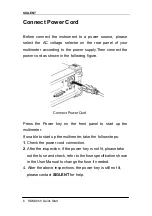
Страница 127: ...ing figure Connect Power Cord Press the Power key on the front panel to start up the multimeter If unable to start up the multimeter take the follow steps 1 Check the power cord connection 2 After the inspection if the power key is not lit please take out the fuse and check refer to the fuse specification shown in the User Manual to change the fuse if needed 4 After the above inspections the power...

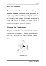
Страница 128: ...ge doesn t match the working voltage while using the setting of the Multimeter s supply voltage must be changed The power selector is located under the power fuse on the rear panel Change the Power Fuse The power fuse is located in the fuse block on the back panel The Multimeter has installed a power fuse before leaving the factory It s a kind of fast melt no burst F300mA 5 20mm one Change the fus...

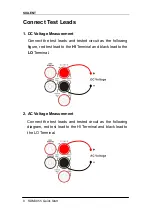
Страница 129: ...the test leads and tested circuit as the following figure red test lead to the HI Terminal and black lead to the LO Terminal 2 AC Voltage Measurement Connect the test leads and tested circuit as the following diagram red test lead to the HI Terminal and black lead to the LO Terminal ...

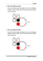
Страница 130: ...eads and tested circuit as the following diagram red test lead to the HI Terminal and black lead to the LO Terminal 4 AC Current Measurement Connect the test leads and tested circuit as the following diagram red test lead to the HI Terminal and black lead to the LO Terminal ...

Страница 131: ...leads and tested circuit as the following diagram red test lead to the HI Terminal and black lead to the LO Terminal 6 4 Wire Resistance Measurement Connect the test leads and tested circuit as the following diagram red test lead to the HI Terminal and black lead to the LO Terminal ...

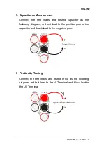
Страница 132: ... tested capacitor as the following diagram red test lead to the positive pole of the capacitor and black lead to the negative pole 8 Continuity Testing Connect the test leads and tested circuit as the following diagram red test lead to the HI Terminal and black lead to the LO Terminal ...

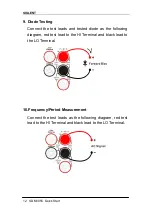
Страница 133: ...t leads and tested diode as the following diagram red test lead to the HI Terminal and black lead to the LO Terminal 10 Frequency Period Measurement Connect the test leads as the following diagram red test lead to the HI Terminal and black lead to the LO Terminal ...

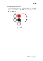
Страница 134: ...LENT SDM3055 Quick Start 13 11 Temperture Measurement Connect the test leads and tested circuit as the following diagram red test lead to the HI Terminal and black lead to the LO Terminal TC and RTD Sensor ...

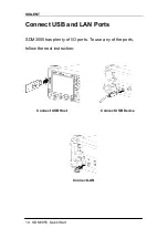
Страница 135: ...SIGLENT 14 SDM3055 Quick Start Connect USB and LAN Ports SDM3055 has plenty of I O ports To use any of the ports follow the next instruction Connect USB Host Connect USB Device Connect LAN ...

Страница 136: ... use the safety lock to lock the multimeter in a fixed place if necessary The methods are as the following 1 Align the key into the keyhole in the vertical direction of the back panel 2 Then rotate clockwise to lock the multimeter 3 Remove the key at last ...

Страница 137: ...wer key 1 Check if the power is correctly connected 2 Check if the power fuse has blown Replace it if necessary 3 If the instrument still can t start up properly please contact SIGLENT 2 The reading doesn t change when connecting an AC current signal 1 Check if the test lead is correctly connected to the current jack or LO jack 2 Check if the fuse in the current location on the back panel has blow...

Страница 138: ... Check if the input is DCI but the measure location is in ACI place 4 USB storage can t be recognized 1 Check if the USB can work normally 2 Make sure that the USB storage being used is of flash type the instrument does not support USB of hardware type 3 Make sure that the capacity of the USB storage is not too large It is suggested that the capacity of the USB matches to the multimeter is no larg...

Страница 139: ...ck Start Contact SIGLENT SIGLENT TECHNOLOGIES CO LTD Address 3 F building NO 4 Antongda Industrial Zone 3rd Liuxian Road Bao an District Shenzhen P R China Tel 0086 755 3661 5186 E mail sales siglent com Http www siglent com ...

Страница 140: ...Remote Manual SDM3055 SDM3055A Digital Mulimeter RC06035 E01A 2014 SIGLENT TECHNOLOGIES CO LTD ...

Страница 141: ... 2 FETCh 7 1 3 INITiate IMMediate 8 1 4 OUTPut TRIGger SLOPe 9 1 5 R 10 1 6 READ 11 1 7 SAMPle COUNt 12 1 8 UNIT TEMPerature C F K UNIT TEMPerature 13 System Command 14 2 1 CALCulate Subsystem 14 2 2 CALCulate LIMit Subsystem 15 2 3 CALCulate TRANsform HISTogram Subsystem 19 2 4 CALCulate SCALe Subsystem 26 2 5 CALCulate AVERage Subsystem 31 2 6 CONFigure Subsystem 35 2 7 DATA Subsystem 44 2 8 MEA...

Страница 142: ...rogram readability use the long form For example consider the keyword VOLTage above You can type VOLT or VOLTage in any combination of upper or lower case letters Therefore VolTaGe volt and Volt are all acceptable Other forms such as VOL and VOLTAG will generate an error Braces enclose the parameter choices The braces are not sent with the command string A vertical bar separates parameter choices ...

Страница 143: ... use both the colon and semicolon TRIG COUN 2 SAMP COUN 2 Using the MIN MAX and DEF Parameters For many commands you can substitute MIN or MAX in place of a parameter In some cases you may also substitute DEF For example consider The following example VOLTage DC RANGe range MIN MAX DEF Instead of selecting a specific value for the range parameter you can substitute MIN to set the range to its mini...

Страница 144: ...erform functions such as reset self test and status operations Common commands always begin with an asterisk are three characters in length and may include one or more parameters The command keyword is separated from the first parameter by a blank space Use a semicolon to separate multiple commands as shown below RST CLS ESE 32 OPC ...

Страница 145: ...n over the letter M or m For your convenience the instrument interprets mV or MV as millivolts but MHZ or mhz as megahertz Likewise MΩ or mΩ is interpreted as megΩ You can use the prefix MA for mega For example MAV is interpreted as megavolts Discrete Parameters Discrete parameters are used to program settings that have a limited number of values like IMMediate EXTernal or BUS They have a short fo...

Страница 146: ...none none Abort a measurement in progress TRIG SOUR IMM Set the trigger source for immediate trigger TRIG COUN 10 Set the trigger source for 10 times INIT Set the trigger state for wait for trigger ABOR Interrupt the measurement This command may be used to abort a measurement when the instrument is waiting for a trigger or for aborting a long measurement or series of measurements ...

Страница 147: ...r source for immediate trigger TRIG COUN 10 Set the trigger source for 10 times INIT Set the trigger state for wait for trigger FETC Read the resulting measurement value The FETch query does not erase measurements from the reading memory You can send the query multiple times to retrieve the same data You can store up to 1 000 measurements in the reading memory of theSDM3055x If reading memory over...

Страница 148: ...ents in reading memory with INITiate is faster than sending measurements to the instrument s output buffer using READ provided you do not send FETCh until done The INITiate command is also an overlapped command This means that after executing INITiate you can send other commands that do not affect the measurements You can store up to 1 000 measurements in the reading memory of the SDM3055x If read...

Страница 149: ...nnector Parameter Typical Return POSitive NEGative default NEGative none Configure DC voltage measurements and make two measurements The signal on the rear panel VM Comp connector will output a positive pulse as each measurement is completed CONF VOLT DC 10 SAMP COUN 2 OUTP TRIG SLOP POS INIT This parameter is set to its default value after a Factory Reset RST or Instrument Preset SYSTem PRESet ...

Страница 150: ...0033E 03 1 22469433E 03 Read and remove the three oldest readings TRIG COUN 3 INIT R 3 The R and DATA REMove queries allow you to periodically remove measurements from the reading memory that would normally cause the reading memory to overflow You can store up to 1 000 measurements in the reading memory of the SDM3055x If reading memory overflows new measurements will overwrite the oldest measurem...

Страница 151: ... measurements from the reading memory You can send the query multiple times to retrieve the same data You can store up to 1 000 measurements in the reading memory of the SDM3055x If reading memory overflows new measurements will overwrite the oldest measurements stored the most recent measurements are always preserved No error is generated but the Reading Mem Ovfl bit bit 14 is set in the Question...

Страница 152: ...et the trigger output signal to rise READ Start the wheel measurement and reading You can use the specified sample count in conjunction with a trigger count TRIGger COUNt which sets the number of triggers to be accepted before returning to the idle trigger state The total number of measurements returned will be the product of the sample count and trigger count You can store up to 1 000 measurement...

Страница 153: ... Return C F K default C C F or K Set to return the result in F UNIT TEMP F Set the temperature measurement unit in F MEAS TEMP Recovery temperature default configuration and read a set of temperaturemeasurements The command also accepts CEL or FAR but the query returns C or F This parameter is set to its default value after a Factory Reset RST or Instrument Preset SYSTem PRESet ...

Страница 154: ...ts histogram data statistics and measurements Parameter Typical Return none none Clear all limits histogram data statistics and measurements CALC CLE IMM CALC CLE IMM The items cleared by this command are cleared synchronously so that the histogram statistics and limit data all restart at the same time that measurements restart ...

Страница 155: ...outside the range of 2 4 to 3 6 V Measurements above 3 6 V will set bit 12 Upper Limit Failed of the Questionable Status Register measurements below 2 4 V will set bit 11 Lower Limit Failed CLS STAT PRES CONF VOLT 10 001 SAMP COUN 100 CALC LIM LOW 2 4 CALC LIM UPP 3 6 CALC LIM STAT ON INIT WAI STAT QUES Typical Response 4096 at least one measurement was above the upper limit Command Summary CALCul...

Страница 156: ...nt register is a read only register that latches events from the condition register While an event bit is set subsequent events corresponding to that bit are ignored Parameter Typical Return none none Clear the limit test results CALC LIM CLECALC LIM CLE IMM This command does not clear measurements in reading memory The instrument clears front panel indications of limits being exceeded and clears ...

Страница 157: ...he upper limit If the limit set is higher than the upper limit the limit value is set to the same limitwill force the same value Limit crossing If a measurement is less than the specified lower limit bit 11 Lower Limit Failed is set in the Questionable Data Condition Register A measurement greater than the specified upper limit sets bit 12 Upper Limit Failed See STATus Subsystem Introduction for f...

Страница 158: ...nstrument clears front panel indications of limits being exceeded and clears bits 11 and 12 in the Questionable Data Register when the measurement function changes or when any of the following commands is executed CALCulate LIMit STATe ON INITiate MEASure function READ CALCulate LIMit CLEar RST SYSTem PRESet The instrument turns this setting OFF when the measurement function is changed or after RS...

Страница 159: ...HISTogram ALL CALCulate TRANsform HISTogram CLEar IMMediate CALCulate TRANsform HISTogram COUNt CALCulate TRANsform HISTogram DATA CALCulate TRANsform HISTogram POINts CALCulate TRANsform HISTogram RANGe AUTO Example This example enables an automatically scaled 100 bin histogram of 1000 DCV measurements It then returns the computed histogram including the lower and upper range values the total mea...

Страница 160: ...red The DATA form returns only the bin data Parameter Typical Return none See Example See Example The bin data includes the following in order The number of measurements less than the lower range value The number of measurements in the each of the bins starting at the lower range value bin The number of measurements greater than the upper range value Range values are real numbers returned in the f...

Страница 161: ...ear the histogramdata CALC TRAN HIST CLE This command does not clear measurements in reading memory To clear statistics limits histogram data and measurement data use CALCulate CLEar IMMediate 2 3 3 CALCulate TRANsform HISTogram COUNt Returns the number of measurements collected since the last time the histogram was cleared Parameter Typical Return none 96 Return the number of measurements used to...

Страница 162: ...easurements below the lower range and one for measurements above the upper range Parameter Typical Return 10 20 40 100 200 400 MIN MAX DEF default 100 100 See Example You can specify the lower and upper range values using CALCulate TRANsform HISTogram RANGe LOWer UPPer Lower and upper range values are computed automatically if CALCulate TRANsform HISTogram RANGe AUTO is ON This parameter is set to...

Страница 163: ...s to set the lower and upper range values OFF the lower and upper range values are specified by CALCulate TRANsform HISTogram RANGe LOWer UPPer Setting the lower or upper range value CALCulate TRANsform HISTogram RANGe LOWer UPPer disables automatic selection of the lower and upper range values CALCulate TRANsform HISTogram RANGe AUTO OFF The instrument restarts automatic range value selection if ...

Страница 164: ...nge values CALCulate TRANsform HISTogram RANGe AUTO OFF Parameter Typical Return 1 0E 15 to 1 0E 15 or 0 0 default or 1 0E 15 to 1 0E 15 1 00000000E 06 See Example If automatic range value selection is enabled CALCulate TRANsform HISTogram RANGe AUTO ON the query returns the computed range value If no histogram data exists 9 91E37 Not a Number is returned Lower and upper range values are computed ...

Страница 165: ... ST ATe ON 1 OFF 0 CALCulate TRANsform HISTogram STATe Enables or disables histogram computation Parameter Typical Return ON 1 OFF 0 default OFF 0 OFF or 1 ON See Example The instrument turns this setting OFF when the measurement function is changed or after RST or SYSTem PRESet ...

Страница 166: ...from the each voltage measurement after the measurement is converted to dBm Note This command applies only to ACV and DCV measurement functions Parameter Typical Return 200 0 dBm to 200 0 dBm default 0 5 00000000E 02 Enable dB scaling with a 10 dB reference reference resistance CALC SCAL DB REF 10 0 CALC SCAL FUNC DB CALC SCAL STAT ON Specifying a reference value disables automatic reference selec...

Страница 167: ... This command applies only to ACV and DCV measurement functions Parameter Typical Return 50 75 93 110 124 125 135 150 250 300 500 600 default 800 900 1000 1200 or 8000Ω 6 00000000E 02 Enable dBm scaling with a reference resistance of 600 Ω CALC SCAL DBM REF 600 CALC SCAL FUNC DBM CALC SCAL STAT ON The instrument sets the reference value to its default value after a Factory Reset RST an Instrument ...

Страница 168: ...dBm 10 log10 measurement 2 reference resistance 1 mW Note This command applies only to ACV and DCV measurement functions Parameter Typical Return DB DBM DBorDBM Enable the DB scaling function referenced to the next measurement taken CALC SCAL FUNC DBM CALC SCAL STAT ON For the dB function the reference value can be automatically selected using the first measurement converted to dBm as the referenc...

Страница 169: ...CALC SCAL DBM REF 50 CALC SCAL FUNC DB CALC SCAL REF AUTO ON CALC SCAL STAT ON READ ON the first measurement made will be used as the reference for all subsequent measurements and automatic reference selection will be disabled For the dB scaling function the first measurement is converted to dBm and CALCulate SCALe DB REFerence is set to the result OFF CALCulate SCALe DB REFerence specifies the re...

Страница 170: ...1 OFF 0 default ON 0 OFF or 1 ON Enable the DB function with automatic reference selection and use the first measurement as the reference value CALC SCAL DBM REF 50 CALC SCAL FUNC DB CALC SCAL REF AUTO ON CALC SCAL STAT ON READ Enabling the scaling function also enables automatic null value selection CALCulate SCALe REFerence AUTO The instrument turns this setting OFF when the measurement function...

Страница 171: ...em calculates measurement statistics Command Summary CALCulate AVERage STATe CALCulate AVERage CLEar IMMediate CALCulate AVERage ALL CALCulate AVERage AVERage CALCulate AVERage COUNt CALCulate AVERage MAXimum CALCulate AVERage MINimum CALCulate AVERage PTPeak CALCulate AVERage SDEViation ...

Страница 172: ...rements CONF FREQ SAMP COUN 100 CALC AVER STAT ON INIT CALC AVER ALL Typical Response 4 10466677E 04 3 13684184E 04 1 75743178E 02 6 74799085E 04 Statistics are cleared when the measurement function changes or when any of these commands is executed CALCulate AVERage STATe ON CALCulate AVERage CLEar INITiate MEASure function READ RST SYSTem PRESet The instrument turns this setting OFF when the meas...

Страница 173: ... queries listed above return individual values Parameter Typical Return none see below Return the statistics of 100 frequency measurements CONF FREQ SAMP COUN 100 CALC AVER STAT ON INIT CALC AVER ALL Typical Response 4 10466677E 04 3 13684184E 04 1 75743178E 02 6 74799085E 04 Statistics are cleared when the measurement function changes or when any of these commands is executed CALCulate AVERage ST...

Страница 174: ...e none Clear the stored statistical data CALC AVER CLE This command does not clear measurements in reading memory Statistics are cleared when the measurement function changes or when any of these commands is executed CALCulate AVERage STATe ON CALCulate AVERage CLEar INITiate MEASure function READ RST SYSTem PRESet To clear statistics limits histogram data and measurement data use CALCulate CLEar ...

Страница 175: ...ne command All other parameters are set to their default values below If no range and sampling speed settings which will restore the default value Measurement Parameter Default Setting Autozero OFF Range AUTO Samples per Trigger 1 sample Trigger Count 1 trigger Trigger Delay 1 trigger Trigger Source Immediate Trigger Slope NEGative Math Functions Disabled Using CONFigure The following example uses...

Страница 176: ...sending measurements to the instrument s output buffer using READ provided you do not send FETCh until done The INITiate command is also an overlapped command This means that after executing INITiate you can send other commands that do not affect the measurements This allows you to check for data availability before initiating a read attempt that might otherwise time out Note that the FETCh query ...

Страница 177: ...sing an external trigger with positive slope rising edge and read the measurement CONF CONT TRIG SOUR EXT SLOP POS READ The range and resolution are fixed at 1 kΩ for continuity tests a 2 wire resistance measurement The instrument beeps if the beeper is enabled for each measurement less than or equal to the continuity threshold The threshold can be passed by SENSe CONTinuity THReshold VALue comman...

Страница 178: ... 2 a range configuration ac current measurements Two measurement and reading CONF CURR AC 2 SAMP COUN 2 READ Typical Response 4 32133675E 04 4 18424606E 04 You can let autoranging select the measurement range or you can manually select a fixed range Autoranging conveniently selects the range for each measurement based on the input signal For fastest measurements use manual ranging autoranging may ...

Страница 179: ...Sure DIODe queries return the measured voltage regardless of its value Use READ or INITiate to start the measurement 2 6 5 CONFigure FREQuency PERiod Sets all measurement parameters and trigger parameters to their default values in the frequency cycle mode Parameter Typical Return none none Configure make and read a default frequency measurement CONF FREQ READ Typical Response 7 79645018E 01 If th...

Страница 180: ...ith default resolution Make and read two measurementsCONF FRES 200 SAMP COUN 2 READ Typical Response 6 71881065E 01 6 83543086E 01 You can let autoranging select the measurement range or you can manually select a fixed range Autoranging conveniently selects the range for each measurement based on the input signal For fastest measurements use manual ranging autoranging may require additional time f...

Страница 181: ...efined sensor selection none type PT100 for RTD only choice or BITS90 EITS90 JITS90 KITS90 NITS90 RITS90 SITS90 TITS9 0 for THER can choose the sensor Configuration RTD measurement Then read measurement results CONF TEMP RTD PT100 READ Typical Response 2 00000000E 02 To change temperature units use UNIT TEMPerature If the input signal is greater than can be measured on the specified manual range t...

Страница 182: ... and read two measurements CONF VOLT AC 200 SAMP COUN 2 READ Typical Response 2 43186951E 02 2 56896019E 02 You can let autoranging select the measurement range or you can manually select a fixed range Autoranging conveniently selects the range for each measurement based on the input signal For fastest measurements use manual ranging autoranging may require additional time for range selection If t...

Страница 183: ...d read two measurements CONF CAP 2uF SAMP COUN 2 READ Typical Response 7 26141264E 10 7 26109188E 10 You can let autoranging select the measurement range or you can manually select a fixed range Autoranging conveniently selects the range for each measurement based on the input signal For fastest measurements use manual ranging autoranging may require additional time for range selection If the inpu...

Страница 184: ...mmands is executed INITiate MEASure function READ RST SYSTem PRESet Command Summary DATA LAST DATA POINts DATA POINts EVENt THReshold DATA REMove 2 7 1 DATA LAST Returns the last measurement taken You can execute this query at any time even during a series of measurements Parameter Typical Return none One measurement with units If no data is available 9 91E37 Not a Number is returned with units Ex...

Страница 185: ...gs WAIT Reads and erases num_readings measurements from the reading memory If fewer than num_readings measurements are available the query will return an error unless the WAIT parameter is specified in which case the query will wait until num_readings measurements are available Parameter Typical Return 1 10000 4 55379486E 04 4 55975533E 04 4 56273556E 04 4 53591347E 04 4 55379486E 04 Read and eras...

Страница 186: ... MEASure VOLTage DC RATio Default Settings for MEASure With the MEASure queries you can select the function range and resolution in one command All other parameters are set to their default values below Parameter Default Setting OFF OFF Range AUTO Samples per Trigger 1 sample Trigger Count 1 trigger Trigger Delay Automatic delay Trigger Source Immediate Trigger Slope NEGative Math Functions Disabl...

Страница 187: ... Then make and read one measurement MEAS CONT The range and resolution are fixed at 1 kΩ for continuity tests a 2 wire resistance measurement The instrument beeps if the beeper is enabled for each measurement less than or equal to the continuity threshold 10 Ω and the actual resistance measurement appears on the display From 10 Ω to 1 2 kΩ the instrument displays the actual resistance measurement ...

Страница 188: ...ponse 4 32133675E 04 4 18424606E 04 You can let autoranging select the measurement range or you can manually select a fixed range Autoranging conveniently selects the range for each measurement based on the input signal For fastest measurements use manual ranging autoranging may require additional time for range selection Autoranging AUTO or DEFault will generate an error if you specify a resoluti...

Страница 189: ...nd immediately triggers a measurement The results are sent directly to the instrument s output buffer Parameter Typical Return none 9 84733701E 01 Configure make and read a default diode measurement MEAS DIOD The range and resolution are fixed for diode tests the range is 2 VDC The FETCh READ and MEASure DIODe queries return the measured voltage regardless of its value ...

Страница 190: ...front panel and returns 9 9E37 from the remote interface Autoranging can be enabled for the input voltage 2 8 5 MEASure RESistance FRESistance range AUTO MIN MAX DEF Sets all measurement and trigger parameters to their default values for 4 wire resistance FRESistance or 2 wire RESistance measurements and immediately triggers a measurement The results are sent directly to the instrument s output bu...

Страница 191: ... built in sensor manufacturers does not support user defined sensor selection none type PT100 only possible value for RTD FRTD or BITS90 EITS90 JITS90 KITS90 NITS90 RITS9 0 SITS90 TITS90 The sensor can be selected for THER Configure the RTD measurement Then read out the measuring results MEAS TEMP RTD PT100 Typical Response 2 00000000E 02 To change temperature units use UNIT TEMPerature For RTD me...

Страница 192: ... range none Configure AC voltage measurements using the 200 V range Then make and read one measurement MEAS VOLT AC 200 Typical Response 2 43186951E 02 2 56896019E 02 You can let autoranging select the measurement range or you can manually select a fixed range Autoranging conveniently selects the range for each measurement based on the input signal For fastest measurements use manual ranging autor...

Страница 193: ...ake and read one measurement MEAS CAP 2uF READ Typical Response 7 26141264E 10 For the Input terminals you can allow the instrument to select the measurement range by autoranging or you can select a fixed range using manual ranging Autoranging decides which range to use for each measurement based on the input signal For faster measurements use manual ranging on each measurement additional time is ...

Страница 194: ...stance PERiod RESistance TEMPerature VOLTage AC VOLTage DC CAPacitance The default is VOLTage DC The short form of the selected function is returned in quotation marks with no optional keywords CONT CURR AC CURR DIOD and so on Select the AC voltage function FUNC VOLT AC If you change the measurement function all measurement attributes of the previous function range resolution etc are remembered If...

Страница 195: ...een AC and DC measurements The parameters are independent for AC and DC measurements Parameter Typical Return ON 1 OFF 0 default OFF 0 OFF or 1 ON Configure AC current measurements using the null function to subtract 100 mA from the measurements Then make two measurements and send them to the instrument s output buffer CONF CURR AC CURR AC NULL STAT ON VAL 100mA SAMP COUN 2 READ Typical Response 9...

Страница 196: ...gure AC current measurements using the null function to subtract 100 mA from the measurements Then make two measurements and send them to the instrument s output buffer CONF CURR AC CURR AC NULL STAT ON VAL 100mA SAMP COUN 2 READ Typical Response 9 92150377E 02 9 98499843E 02 Specifying a null value disables automatic null value selection SENSe CURRent AC DC NULL VALue AUTO OFF To use the null val...

Страница 197: ...VAL AUTO ON READ Typical Response 4 67956379E 08 2 33978190E 08 When automatic reference selection is ON the first measurement made is used as the null value for all subsequent measurements SENSe CURRent AC DC NULL VALue will be set to this value Automatic null value selection will be disabled When automatic null value selection is disabled OFF the null value is specified by this command SENSe CUR...

Страница 198: ...s AUTO autorange 2 00000000E 01 Configure AC current measurements using the 2 A range Make and read two measurements CONF CURR AC CURR AC RANG 2 SAMP COUN 2 READ Typical Response 3 53049833E 04 3 54828343E 04 Selecting a fixed range SENSe function RANGe disables autoranging If the input signal is greater than can be measured on the specified manual range the instrument displays the word Overload o...

Страница 199: ... the instrument selects the range based on the input signal This parameter is set to its default value after a Factory Reset RST or Instrument Preset SYSTem PRESet 2 9 6 SENSe CURRent DC NPLC PLC MIN MAX DEF SENSe CURRent DC NPLC MIN MAX DEF Sets the integration time in number of power line cycles PLC for DC current measurements Integration time is the period that the instrument s analog to digita...

Страница 200: ...ent DC FILTer STATe Dc current measurement mode filter switch configuration Parameter Typical Return ON 1 OFF 0 default ON 0 OFF or 1 ON Open the dc current mode filter CONF CURR AC CURR FILTER ON This parameter is set to its default value after a Factory Reset RST or Instrument Preset SYSTem PRESet ...

Страница 201: ... Enables or disables the null function for frequency and period measurements This parameter is shared between frequency and period measurements Parameter Typical Return ON 1 OFF 0 default OFF 0 OFF or 1 ON Configure frequency measurements using the null function to subtract 1kHz from the measurements Make and read two measurements CONF FREQ FREQ NULL STAT ON VAL 1 kHz SAMP COUN 2 READ Typical Resp...

Страница 202: ...easurements using the null function to subtract 1kHz from the measurements Make and read two measurements FREQ NULL STAT ON VAL 1 kHz SAMP COUN 2 READ Typical Response 1 15953012E 02 1 07954466E 02 Specifying a null value disables automatic null value selection SENSe FREQuency PERiod NULL VALue AUTO OFF To use the null value the null state must be on SENSe FREQuency PERiod NULL STATe ON This param...

Страница 203: ...ponse 1 15953012E 02 1 07954466E 02 When automatic reference selection is ON the first measurement made is used as the null value for all subsequent measurements SENSe FREQuency PERiod NULL VALue will be set to this value Automatic null value selection will be disabled When automatic null value selection is disabled OFF the null value is specified by this command SENSe FREQuency PERiod NULL VALue ...

Страница 204: ...0V 2 00000000E 01 Configures frequency measurements using the 10 VAC range Make and read two measurements CONF FREQ FREQ VOLT RANG 20 SAMP COUN 2 READ Selecting a fixed range SENSe function RANGe disables autoranging If the input voltage is too large for the selected voltage range manual ranging the instrument displays the word Overload on the front panel and returns 9 9E37 from the remote interfa...

Страница 205: ...surements Parameter Typical Return ON 1 OFF 0 default ON 0 OFF or 1 ON Configure frequency measurements and perform an immediate AC voltage autorange Make and read two measurements CONF FREQ FREQ VOLT RANG AUTO ONCE SAMP COUN 2 READ With autoranging enabled the instrument selects the range based on the input signal Selecting a fixed range SENSe function RANGe disables autoranging This parameter is...

Страница 206: ...PLC PLC MIN MAX DEF SENSe RESistance FRESistance NPLC MIN MAX DEF Sets the integration time in number of power line cycles PLC for all alternating current measurements Integration time is the period that the instrument s analog to digital A D converter samples the input signal for a measurement Parameter Typical Return 0 3 1 10 default 1 On the front panel 0 3 1 10 corresponds to the Speed menu un...

Страница 207: ...sistance measurements using the null function to remove 100 mΩ of wiring resistance Make and read two measurements CONF RES RES NULL STAT ON VAL 0 1 SAMP COUN 2 READ Enabling the scaling function also enables automatic null value selection SENSe RESistance FRESistance NULL VALue AUTO ON To set a fixed null value use this command SENSe RESistance FRESistance NULL VALue The instrument disables the n...

Страница 208: ...nts using the null function to remove 100 mΩ of wiring resistance Make and read two measurements CONF RES RES NULL STAT ON VAL 0 1 SAMP COUN 2 READ Typical Return 1 04530000E 02 1 04570000E 02 Specifying a null value disables automatic null value selection SENSe RESistance FRESistance NULL VALue AUTO OFF To use the null value the null state must be on SENSe RESistance FRESistance NULL STATe ON Thi...

Страница 209: ...automatic reference selection is ON the first measurement made is used as the null value for all subsequent measurements SENSe RESistance FRESistance NULL VALue will be set to this value Automatic null value selection will be disabled When automatic null value selection is disabled OFF the null value is specified by this command SENSe RESistance FRESistance NULL VALue The instrument enables automa...

Страница 210: ... 2 kΩ 20 kΩ 200 kΩ 2 MΩ 10 MΩ 100 MΩ default 2 kΩ 2 00000000E 03 Configure 2 wire resistance measurements using the 10 kΩ range Then make and read one measurement CONF RES RES RANG 2E3 SAMP COUN 2 READ Selecting a fixed range SENSe function RANGe disables auto ranging If the input signal is greater than can be measured on the specified manual range the instrument displays the word Overload on fron...

Страница 211: ...forms an immediate autorange and then turns autoranging off Parameter Typical Return ON 1 OFF 0 default ON 0 OFF or 1 ON Configure 2 wire resistance measurements and perform an immediate autorange Make and read two measurements CONF RES RES RANG AUTO ONCE SAMP COUN 2 READ Autoranging goes down a range at less than 10 of range and up a range at greater than 120 of range Selecting a fixed range SENS...

Страница 212: ...Nsducer POINt 2 9 19 SENSe TEMPerature NULL STATe ON 1 OFF 0 SENSe TEMPerature NULL STATe Enables or disables the null function for temperature measurements Parameter Typical Return ON 1 OFF 0 default ON 0 OFF or1 ON Configure 4 wire RTD measurements using the null function to subtract 25 TEMP NULL STAT ON VAL 25 Enabling the scaling function also enables automatic null value selection SENSe TEMPe...

Страница 213: ... default 0 0 00000000E 00 Configure 4 wire RTD measurements using the null function to subtract 25 TEMP NULL STAT ON VAL 25 Specifying a null value disables automatic null value selection SENSe TEMPerature NULL VALue AUTO OFF To use the null value the null state must be on SENSe TEMPerature NULL STATe ON This parameter is set to its default value after a Factory Reset RST Instrument Preset SYSTem ...

Страница 214: ...he first measurement made is used as the null value for all subsequent measurements SENSe TEMPerature NULL VALue will be set to this value Automatic null value selection will be disabled When automatic null value selection is disabled OFF the null value is specified by this command SENSe TEMPerature NULL VALue The instrument enables automatic null value selection when the null function is enabled ...

Страница 215: ...Fine MDEFine THER RTD TRANsducer transducer Set the current effect of sensors Parameter Typical Return PT100 RTD BITS90 EITS90 JITS90 KITS90 NIT S90 RITS90 SITS90 TITS90 THER none Set the THER KITS90 as the current sensor TEMP MDEF THER TRAN KITS90 The information can be obtained through the SENSe TEMPerature UDEFine MDEFine THER RTD TRANsducer LIST This command will respond to the defaultsensor K...

Страница 216: ...arameter Typical Return PT100 RTD BITS90 EITS90 JITS90 KITS90 NIT S90 RITS90 SITS90 TITS90 THER 1 6 45800 270 0000 2 6 44100 260 0000 The return value to serial number voltage value temperature point of the format arrangement comma separated between different points Inquiry detailed information of THER KITS90 definition TEMP MDEF THER TRAN POIN KITS90 ...

Страница 217: ... measurements Note This parameter is not shared between AC and DC measurements The parameters are independent for ACand DC measurements Parameter Typical Return ON 1 OFF 0 default OFF 0 OFF or1 ON Configure AC voltage measurements using the null function to subtract 100 mV from the measurements Make and read two measurements CONF VOLT AC VOLT AC NULL STAT ON VAL 100mV SAMP COUN 2 READ Typical Resp...

Страница 218: ...1 00000000E 01 Configure AC voltage measurements using the null function to subtract 100 mV from the measurements Make and read two measurements CONF VOLT AC VOLT AC NULL STAT ON VAL 100mV SAMP COUN 2 READ Typical Response 1 03625390E 00 1 03641200E 00 Specifying a null value disables automatic null value selection SENSe VOLTage AC DC NULL VALue AUTO OFF To use the null value the null state must b...

Страница 219: ...tion VOLT AC NULL VAL AUTO ON READ Typical Response 0 00000000E 00 0 01230000E 00 When automatic reference selection is ON the first measurement made is used as the null value for all subsequent measurements SENSe VOLTage AC DC NULL VALue will be set to this value Automatic null value selection will be disabled When automatic null value selection is disabled OFF the null value is specified by this...

Страница 220: ...00E 00 Configure AC voltage measurements using the 100 V range Make and read two measurements CONF VOLT AC VOLT AC RANG 2 SAMP COUN 2 READ Typical Response 8 21650028E 03 8 17775726E 03 Selecting a fixed range SENSe function RANGe disables autoranging If the input signal is greater than can be measured on the specified manual range the instrument displays the word Overload on front panel and retur...

Страница 221: ...nt for AC and DC measurements Parameter Typical Return ON 1 OFF 0 default ON 0 OFF or1 ON Configure DC voltage measurements and perform an immediate autorange Make and read two measurements CONF VOLT AC VOLT AC RANG AUTO ONCE SAMP COUN 2 READ Typical Response 8 36187601E 03 8 34387541E 03 Under the condition of opening in automatic adjustment range the instrument is based on the input signal selec...

Страница 222: ...al A D converter samples the input signal for a measurement A longer integration time gives better measurement resolution but slower measurement speed Parameter Typical Return 0 3 1 10 default 1 On the front panel 0 3 1 10 corresponds to the Speed menu under fast middle slow 1 00000000E 01 Configure DC voltage measurements using a 10 PLC integration time CONF VOLT DC VOLT DC NPLC 10 This parameter...

Страница 223: ...N This parameter is set to its default value after a Factory Reset RST or Instrument Preset SYSTem PRESet 2 9 32 SENSe VOLTage DC IMPedance impedance SENSe VOLTage DC IMPedance Select the input impedance of DC voltage measurement mode Parameter Typical Return 10M 10G default open 10M Select 10M as the input impedance VOLT DC IMP 10M This parameter is only valid in the 200mV and 2V gear to This par...

Страница 224: ...rn ON 1 OFF 0 default ON 0 OFF or1 ON Use zero functions from the measured value minus 100 nf to configure the capacitance measurement Make and read two measurements sent the results to the output buffer of the instrument CONF CAP CAP NULL STAT ON VAL 100nF SAMP COUN 2 READ Typical Response 4 79899595E 10 4 79906446E 10 Enable the scaling function will also enable automatic zero value choice SENSe...

Страница 225: ...measurements Make and read two measurements sent the results to the output buffer of the instrument CONF CAP CAP NULL STAT ON VAL 100nF SAMP COUN 2 READ Typical Response 4 79899595E 10 4 79906446E 10 Specifies the return to zero will disable automatic selection to zero SENSe Capacitance NULL VALue AUTO OFF To use the zero value must first open thezeroswitching SENSe Capacitance NULL STATeON This p...

Страница 226: ... reference selection is ON the first measurement made is used as the null value for all subsequent measurements SENSe Capacitance NULL VALue will be set to this value Automatic null value selection will be disabled When automatic null value selection is disabled OFF the null value is specified by this command SENSe Capacitance NULL VALue The instrument enables automatic null value selection when t...

Страница 227: ...sure Make and read two measurements CONF CAP CAP RANG 2E 6 SAMP COUN 2 READ Typical Response 7 28283777E 10 7 28268544E 10 Choose the fixed range SENSe function RANGe disable the automatic adjustment range If the input signal is greater than can be measured on the specified manual range the instrument displays the word Overload on front panel and returns 9 9E37 from the remote interface This param...

Страница 228: ...r1ON Configure AC current measurement and executed immediately Make and read two measurements CONF VOLT AC VOLT AC RANG AUTO ONCE SAMP COUN 2 READ Typical Response 8 36187601E 03 8 34387541E 03 The situation in the automatic adjustment range enabled the input signal range based on the instrument This parameter is set to its default value after a Factory Reset RST Instrument Preset SYSTem PRESet or...

Страница 229: ... SENSe CONTinuity THReshold VALue value MIN MAX DEF SENSe CONTinuity THReshold VALue Disable or enable automatic adjustment range Parameter Typical Return 0 2000 Ω default 0 2 00000000E 03 Sets the threshold resistance to 2000 CONT THR VAL 2000 This parameter is set to its default value after a Factory Reset RST Instrument Preset SYSTem PRESet or CONFigure function ...

Страница 230: ... is non volatile it is not changed by power cycling a Factory Reset RST or an Instrument Preset SYSTem PRESet 2 10 2 SYSTem COMMunicate LAN IPADdress address SYSTem COMMunicate LAN IPADdress CURRent STATic Assigns a static Internet Protocol IP address for the instrument Parameter Typical Return Command nnn nnn nnn nnn Query CURRent STATic default CURRent Default 169 254 3 5 192 168 1 101 Set a sta...

Страница 231: ...fault 255 255 0 0 Query CURRent STATic default CURRent 255 255 255 0 Set the subnet mask SYST COMM LAN SMAS 255 255 255 0 A value of 0 0 0 0 or 255 255 255 255 indicates that subnetting is not being used CURRent returns address currently being used by the instrument STATic returns static address from non volatile memory This address is used if DHCP is disabled or unavailable This setting is non vo...

Страница 232: ...ements CONF VOLT DC SAMP COUN 5 TRIG COUN 10 READ Typical Response 1 85425399E 04 50 measurements You can use the specified trigger count in conjunction with a sample count SAMPle COUNt which sets the number of samples to be made per trigger In this case the number of measurements returned will be the sample count multiplied by the trigger count You can store up to 1 000 measurements in the readin...

Страница 233: ...ct delay For example if you send TRIG DEL 500 ms and then TRIG DEL the actual delay may be 5 00000753E 01 By default TRIGger DELay AUTO is ON The instrument automatically determines the delay based on function range and integration time see Automatic Trigger Delays However you may need to set a delay longer than the automatic delay for long cables high capacitance or high impedance signals If you ...

Страница 234: ... DC voltage measurements with an automatic delay between each measurement CONF VOLT DC 10 SAMP COUN 5 TRIG DEL AUTO 1 READ Typical Response 3 07761360E 03 1 16041169E 03 5 60585356E 06 1 21460160E 04 2 85898 531E 04 Selecting a specific trigger delay using TRIGger DELay disables the automatic trigger delay This parameter is set to its default value after a Factory Reset RST or Instrument Preset SY...

Страница 235: ...ig BNC connector Parameter Typical Return POSitive NEGative default NEGative POS orNEG Return ten sets of five DC voltage measurements using a positive going external trigger to start each measurement set CONF VOLT DC SAMP COUN 5 TRIG COUN 10 TRIG SOUR EXT SLOP POS READ Typical Response 1 85425399E 04 50 measurements This parameter is set to its default value after a Factory Reset RST or Instrumen...

Страница 236: ...ecified by OUTPut TRIGger SLOPe is received If the instrument receives an external trigger before it is ready it will buffer one trigger Parameter Typical Return IMMediate EXTernal BUS default IMMediate IMM EXT or BUS Return ten sets of five DC voltage measurements using a positive going external trigger to start each measurement set CONF VOLT DC SAMP COUN 5 TRIG COUN 10 TRIG SOUR EXT SLOP POS REA...

Отзывы: