MapIT G2 Hardware Installation Training Manual
Confidential – June 2014
6
•
It communicates via TCP/IP with the EagleEye database
•
The MCP supplies power to SPPs and SFEs when connected directly to these
items. It does not supply power to DCPs.
Distribution Control Panel (DCP) Functions
•
The DCP relays information on connected SPP/SFEs to the MCP
•
Relays information on patch connections between SPPs/SFEs to the MCP
•
Communicates with the MCP via a Control Bus Cable
•
Supplies power to SPPs/SFEs
•
The DCP has its own power supply. It is not powered from the MCP via the
Control Bus Cable
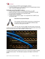
Patch Cord Connections Example:
When a MapIT G2 Patch Cable is inserted into a monitored port,
the probe located in the boot of the MapIT G2 Patch Cable
touches the sensor pad on the SPP.
When the other end of the MapIT G2 Patch Cable is inserted into
another monitored port, a connection is created between the two sensors via a 9
th
wire
that connects the two probes inside the MapIT G2 Patch Cable.
The MapIT G2 Smart Panel detects the connection and port ID information is passed
between the two panels. This information is passed to the Master Control Panel
(MCP).


