MapIT G2 Hardware Installation Training Manual
Confidential – June 2014
13
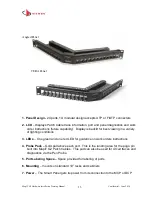
Angled Panel
TERA Panel
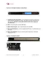
1. Panel Design -
24 ports, 1U modular design accepts UTP or F/UTP connectors
2. LCD
– Displays Patch Cable trace information, port and panel diagnostics and work
order instructions (future capability). Display is backlit for best viewing in a variety
of lighting conditions
3. LEDs
– One green and one red LED for guidance on work orders instructions
4. Probe Pads
–
Gold pad above each port.
This is the
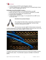
landing area for the pogo pin
built into MapIT G2 Patch Cables. This pad can also be used for circuit traces and
diagnostics via the Pen Probe
5. Port Labeling Space
–
Space provided for labeling of ports
6. Mounting
– mounts on standard 19” racks and cabinets
7. Power
– The Smart Panel gets its power from its connection to the MCP or DCP


