37
Siemens Building Technologies
Fire Safety & Security Products
10.2008
For ease of installation, trunk video and network data cabling always go together.
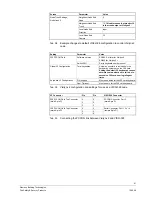
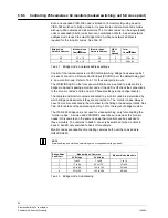
In order to use each VIS3I-328 unit in a network, you need to set up its
configuration file using the VisiPC Configurator software. As an example, the
changes that are required to the VisiPC Configurator software screens for each of
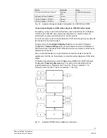
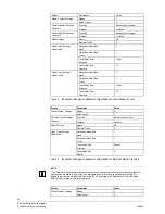
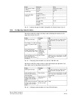
the three units shown in Fig. 13 are shown in Tab. 23, Tab. 24 and Tab. 24. Each
unit configuration should be saved in a separate new file. Full details of VisiPC
operation are detailed in its User Manual.
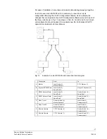
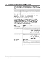
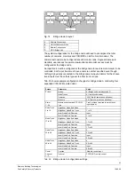
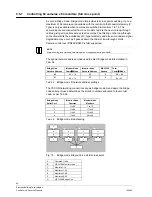
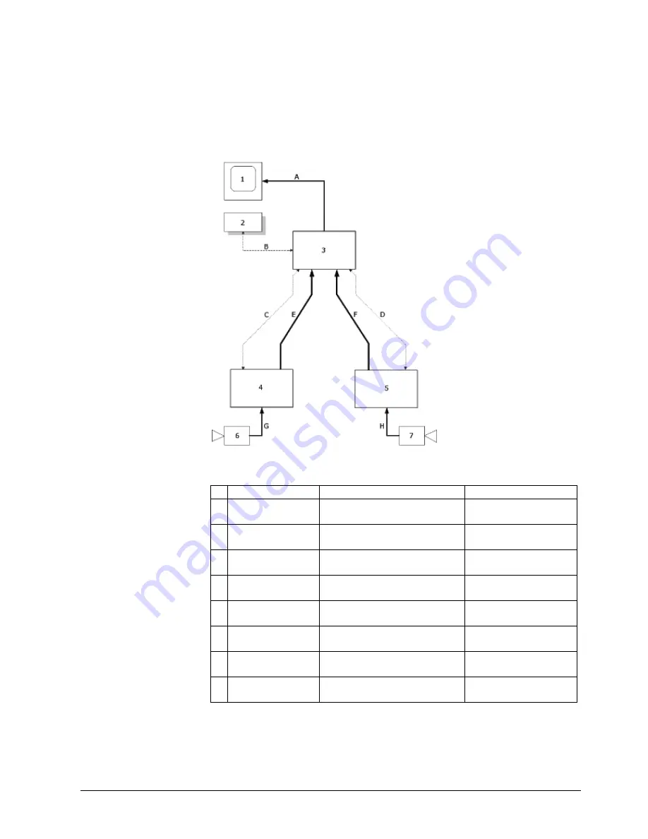
Fig. 13
Example 3-node VIS3I-328 interconnection block diagram
Connection
From
To
A
Monitor
Local Node (3)
Monitor Output 1
CCTV Monitor (1)
B
Keyboard RS485 Data
Local Node (3)
Serial Port 10
Visilynx 3 Keyboard (2)
C
RS232 Network Data
Local Node (3)
Serial Port 1
Remote Node 1 (4)
Serial Port 1
D
RS232 Network Data
Local Node (3)
Serial Port 3
Remote Node 2 (5)
Serial Port 1
E
Video Trunk 1
Remote Node 1 (4)
Monitor Output 8
Local Node (3)
Camera input 31
F
Video Trunk 2
Remote Node 2 (5)
Monitor Output 8
Local Node (3)
Camera input 32
G Remote Camera
CCTV Camera (6)
Remote Node 1 (4)
Camera Input 1
H
Remote Camera
CCTV Camera (7)
Remote Node 2 (5)
Camera Input 1


