10
Siemens Building Technologies
Fire Safety & Security Products
10.2008
6 Description
of
equipment
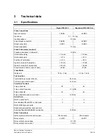
The Visilynx 3i (VIS3I-328) is a 32 loop-through input by 8-output full cross-point
video matrix node contained in a 19” wide by 3U high enclosure.
You can connect two identical units together using an expansion cable to double
the size of the video matrix to 64 loop-through input by 16-output full cross-point
switcher. In this configuration, you set one of the two units to be the Master and
this can connect to a Visilynx control network, and you set the other to be the Slave
unit.
You can connect up to 127 nodes together to form a distributed video switching
network. The video connections between nodes are made by trunk connections.
In a networked system, a keyboard at one node may view and control cameras,
VCR/DVRs and multiplexers at any other node. It may also respond to alarms from
other nodes. The number of video inputs from remote nodes that can be viewed at
any one time is governed by the number of available trunk connections between
the nodes.
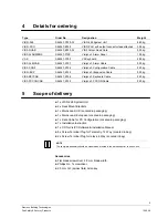
You can expand any VIS3I-328, by fitting up to two optional Visilynx 3 quad cards
(Type VIS3-QUAD). In a single VIS3I-328 with 8 monitor outputs, each quad card
makes available the equivalent of an additional 4 monitor outputs.
The main user interface device of the VIS3I-328 system is the Visilynx 3 keyboard.
A single keyboard may be powered by a single VIS3I-328, and a further 15
keyboards with local power supplies may be addressed. You must not connect a
keyboard to both power sources at once.
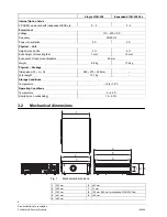
Each VIS3I-328 is designed to be used free standing (as supplied) or fitted into a
standard 19” rack cabinet.
The VIS3I-328 is supplied with configuration and test software called VisiPC, which
you should install onto a suitable PC. This forms the heart of the system's
configuration and test capability.
This manual is designed to cover basic operation. To be able to understand and
use advanced features such as networking it is recommended to attend a product
training course.
General
The VIS3I-328 is made up of these mechanical and electrical subsystems:
z
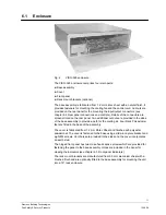
Enclosure (see chapter 6.1 Enclosure)
z
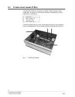
Printed Circuit Boards (see chapter 6.2 Printed circuit boards (PCBs)).
z
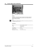
Power Supply Module (see chapter 6.3 Power supply module VIS3I-PSU)
z
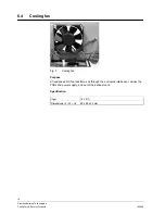
Cooling fan (see chapter 6.4 Cooling fan)
z
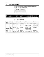
Front panel indicators (see chapter 6.5 Front panel indicators)
z
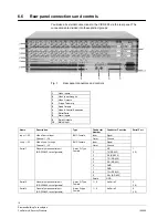
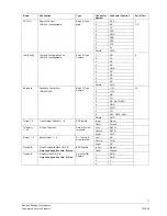
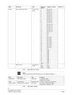
Rear panel connections and controls (see chapter 6.6 Rear panel connections
and controls)
z
Firmware and software (see chapter 6.7 Firmware and software)
z
Quad cards (see chapter 6.8 Quad card VIS3-QUAD)


