43
Siemens Building Technologies
Fire Safety & Security Products
10.2008
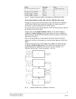
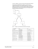
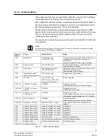
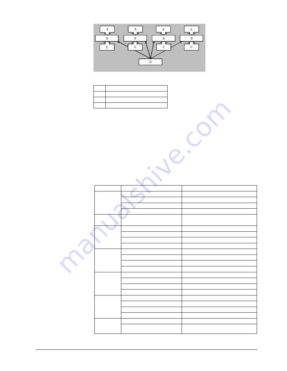
Fig. 14
Bridge mode A layout
A Camera
Connections
B
VIS3I-328 Monitor Node
C Monitor
Connections
D
VIS3I Bridge Unit
The system configuration for the bridge node will need to encompass the total
number of cameras, monitors and VCR/MPX on all the ‘monitor nodes’. The
camera text needs to be configured at each monitor node. Keyboard access to
monitors, user access to camera view/control and monitor access must be
configured at the bridge node.
An input trunk must be configured at the bridge node for each remote monitor to be
controlled. Each input trunk must have a camera number specified even though
nothing is physically connected to the bridge camera inputs. Alarms for the chosen
trunk inputs must have their type set to either trunk or none.
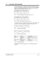
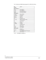
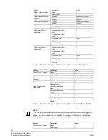
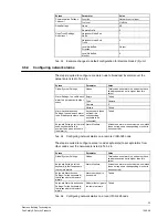
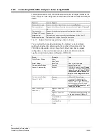
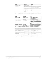
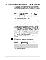
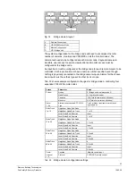
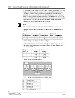
Tab. 33 shows example configuration changes for bridge mode A controlling four
expanded VIS3I-328 remote nodes.
Screen Parameter
Value
Nodes
5 (Bridge node is always node 5)
Node Trunks
4 (1 per Monitor node)
Cameras
256 (Total of cameras on all nodes)
System
Monitors
64 (Total of monitors on all nodes)
Alarm
1 - 64
Alarms on keyboards & PCCON:
Type
Trunk or None (required to permit trunk
inputs below)
Neighbour Node End: Node
1
Neighbour Node End: Trunk
1 to 16
Local Node End: Direction
Input
Node Trunk
1 to 16
Local Node End: Camera
1 to 16
Neighbour Node End: Node
2
Neighbour Node End: Trunk
17 to 32
Local Node End: Direction
Input
Node Trunk
17 to 32
Local Node End: Camera
17 to 32
Neighbour Node End: Node
3
Neighbour Node End: Trunk
33 to 48
Local Node End: Direction
Input
Node Trunk
33 to 48
Local Node End: Camera
33 to 48
Neighbour Node End: Node
4
Neighbour Node End: Trunk
49 to 64
Local Node End: Direction
Input
Node Trunk
49 to 64
Local Node End: Camera
49 to 64
Function
Network control input
Comm.
Channel
1 - 4
Protocol
PCCON2/3 remote control
Tab. 33
Bridge mode A configuration settings

