background image

Commissioning 


4.3 Creating a STEP 7 project 


Connecting SIMOVERT MASTERDRIVES MC to the Technology-CPU 

36


Product Information, 03/2008, A5E00272072-05 

Technology CPU 

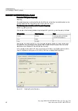
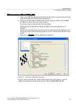
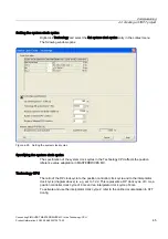
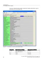
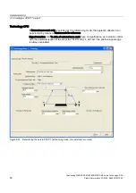
The settings of the encoder used that are required for the Technology CPU are listed in the 

following table. Only the input values listed in the tables are evaluated for the respective 

encoder.  
If a fine resolution 0 (standard) is set in the Technology CPU, this means a fine resolution of 

2

11 

= 2048. If a different value is set (e.g. 1024), this means the actual fine resolution. 

Encoder parameters in SIMOTION are specified using parameters in the axis configuration 

windows or using the configuration data in the expert list as 

"TypeOfAxis.NumberOfEncoders.Encoder_1.xxx". The following assignments apply to the 

axis configuration windows:  


Parameter 

Meaning 

Encoder type 

TypeOfAxis.NumberOfEncoders.Encoder_1.encoderType 

Encoder mode 

TypeOfAxis.NumberOfEncoders.Encoder_1.encoderMode 

Resolution 

TypeOfAxis.NumberOfEncoders.Encoder_1.IncEncoder.IncResolution 
TypeOfAxis.NumberOfEncoders.Encoder_1.AbsEncoder.AbsResolution 

Number of data bits 

TypeOfAxis.NumberOfEncoders.Encoder_1.AbsEncoder.AbsDataLength 

Multiplication factor of 

the cyclic encoder 

actual value 

TypeOfAxis.NumberOfEncoders.Encoder_1.IncEncoder.IncResolutionMultiplierCyclic 
TypeOfAxis.NumberOfEncoders.Encoder_1.IncEncoder.AbsResolutionMultiplierCyclic 

Multiplication factor of 

the absolute encoder 

actual value 

TypeOfAxis.NumberOfEncoders.Encoder_1.AbsEncoder.AbsResolutionMultiplierAbsolute 

Содержание SIMOVERT MASTERDRIVES MC Series

Страница 1: ..._______ ______________ ______________ ______________ Definitions and warnings 1 Hardware Requirements 2 Software Requirements 3 Commissioning 4 MASTERDRIVES MC commissioning tool 5 SIMATIC Connecting SIMOVERT MASTERDRIVES MC to the Technology CPU Product Information 03 2008 A5E00272072 05 ...

Страница 2: ...on of a device system may only be performed by qualified personnel Within the context of the safety notes in this documentation qualified persons are defined as persons who are authorized to commission ground and label devices systems and circuits in accordance with established safety practices and standards Prescribed Usage Note the following WARNING This device may only be used for the applicati...

Страница 3: ...ssioning procedure 13 4 2 Table of the settings 14 4 3 Creating a STEP 7 project 15 4 3 1 Configuring the hardware 15 4 3 2 Creating an axis 26 4 3 3 Referencing 49 4 3 4 Measuring function 57 4 3 5 Activating a brake 64 4 3 5 1 Vertical axis application case 64 4 3 5 2 Activating braking sequential control in the axis 65 4 3 5 3 Activating the braking control in the MASTERDRIVE MC 70 4 4 Basic co...

Страница 4: ...Table of contents Connecting SIMOVERT MASTERDRIVES MC to the Technology CPU 4 Product Information 03 2008 A5E00272072 05 ...

Страница 5: ...m the MASTERDRIVES series The script file to connect SIMOVERT MASTERDRIVES Motion Control to SIMATIC with the standard telegram frame 5 is available at no cost It may be copied modified and used or passed on to third parties However in the case of it being passed on to a third party it must be in its full and unmodified form and all copyright conditions must be observed The commercial distribution...

Страница 6: ...Definitions and warnings Connecting SIMOVERT MASTERDRIVES MC to the Technology CPU 6 Product Information 03 2008 A5E00272072 05 ...

Страница 7: ...perated at its rated power PROFIBUS communication module CBP2 A CBP2 must be installed Whether the converter has a CBP2 or not can be identified in the monitoring parameter r826 x If the monitoring parameter is not displayed then initially the basic unit should be commissioned as described in Chapter Basic commissioning MASTERDRIVES MC The index x designates the slot in which the CBP2 is plugged i...

Страница 8: ...Hardware Requirements 2 1 Converter Connecting SIMOVERT MASTERDRIVES MC to the Technology CPU 8 Product Information 03 2008 A5E00272072 05 ...

Страница 9: ...the AC Edition PROFIBUS communication module CBP2 Version V2 23 or higher can be identified in r69 x and r828 x If the monitoring parameter is not displayed then initially the basic unit should be commissioned as described in Chapter Basic commissioning MASTERDRIVES MC The index x designates the slot at which the CBP2 is plugged in Index 1 means the basic device module Index 2 the module in slot A...

Страница 10: ...mation 03 2008 A5E00272072 05 3 1 2 Upgrading the software Procedure 1 The Drive Monitor or Drive ES may only access the converter RAM for upgrading the firmware Figure 3 1 Drive Monitor accesses the RAM of the MC 2 Open the window for the option card download Figure 3 2 Opening the Option Card Download window ...

Страница 11: ...hich the CBP2 is installed Activate the Activate diagnostics checkbox Note You can download the current firmware version from the Internet http support automation siemens com Entry ID 10999663 Figure 3 3 Settings in the Option Card Download window 4 Right click a free area of the screen The following window opens Figure 3 4 Additional settings for the download 5 Enter a program length of 128KB and...

Страница 12: ... 05 6 Activate the Check button This then changes into Start Download Click on this button The EEPROM blocks are deleted The following window opens Figure 3 5 Start of the script file download 7 Start the download with Start Result After the download you can read out the new firmware release of the CBP2 from parameters r69 x and r828 x ...

Страница 13: ...e manager are used to enter the settings for the Technology CPU Settings which have to be made both in the Technology CPU and in the MASTERDRIVES MC are specifically highlighted In the second part of the commissioning the MASTERDRIVES MC is parameterized The guided basic unit commissioning procedure and a pre programmed script file for connection to the Technology CPU are used Various parameter se...

Страница 14: ...table DP cycle ________ ms Incremental encoder Specify Encoder Absolute encoder Reference cam encoder zero mark Only encoder zero mark Only reference cam 1 Zero position to the right of the reference cam Referencing mode 1 Zero position to the left of the reference cam Measuring function Encoder type Order No 1Fxxxxx _ xxxx x _ xx Rated motor speed max speed axis ______ 1 min Master application cy...

Страница 15: ...rst create a new project under a freely selectable name A new S7 300 station is created with the menu command Insert Station SIMATIC 300 station The Hardware Configuration is opened by double clicking on the element Hardware in the SIMATIC 300 station The application HW Config starts and opens the empty SIMATIC 300 station Now select the profile rail from the hardware Catalog SIMATIC Technology CP...

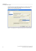
Страница 16: ...ies PROFIBUS interface DP DRIVE In the window Properties PROFIBUS interface DP DRIVE S0 S3 1 window press the New button in order to assign a network to the DP drive interface The PROFIBUS configuration is set in the dialog box that is displayed Please select the Network Settings tab Enter PROFIBUS address 2 as the highest address Set a transmission rate of 12 Mbit s on the bus andDP as profile Fi...

Страница 17: ...imes for the particular motion control type from the following table DP cycle time Motion Control Motion Control Performance 2 1 5 ms X 2 ms X X 3 ms X X X Possible setting Setting not possible The other described settings are all shown for a DP cycle of 3 ms You can also make the settings using the properties dialog boxes of the drives The isochronous DP cycle and the cycle time are then automati...

Страница 18: ...ngs with OK the configured objects are added to the SIMATIC 300 station Figure 4 5 SIMATIC 300 station Note The X1 MPI DP interface in the subrack is not networked for this example It is set as default to a communications for MPI with 187 5 Mbaud In order to download the technology system data onto the module the data transfer rate of the interface should be set to 1 5 Mbaud ...

Страница 19: ...072 05 19 Add a MASTERDRIVES Compact Plus unit to PROFIBUS e g with the address 3 this is in the hardware catalog under CPU 317T PROFIBUS DP DRIVE drives MASTERDRIVES CBP2 Figure 4 6 Attaching a MASTERDRIVES Motion Control Plus to PROFIBUS In the next window Properties Drive select the firmware version of the unit and acknowledge with OK ...

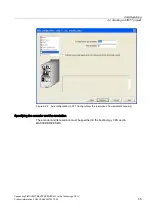
Страница 20: ...MOVERT MASTERDRIVES MC to the Technology CPU 20 Product Information 03 2008 A5E00272072 05 In the Configuration tab of the DP Slave Properties window select the pre assignment of the Standard message frame 5 Figure 4 7 Setting standard telegram 5 at the slave ...

Страница 21: ...eration tab activate the setting Synchronize drive to equidistant DP cycle Figure 4 8 Activating clock cycle synchronization Specifying the DP cycle The DP cycle must be set in the Technology CPU and in the MASTERDRIVES MC Technology CPU In the Technology CPU the pulse frequency is set just the same as at MASTERDRIVES MC determines the DP cycle and aligned to the DP cycle ...

Страница 22: ...ime This results in the following relationships between DP cycle time pulse frequency and task DP cycle time Pulse frequency Task 1 5 ms 5 3 kHz 3 only possible with Motion Control Performance 2 2 ms 8 kHz 4 3 ms 5 3 kHz 4 This means for a DP cycle of e g 3 ms the pulse frequency P340 5 3 kHz In this case the restriction for pulse frequencies greater than 5 0 kHz should be taken into account as de...

Страница 23: ...rom the pulse frequency of 5 3 kHz from 3 019 ms with 3 000 ms and click on Align The following settings are made when the button is pressed The equidistant bus cycle is activated The DP cycle in the master system is aligned with the drive properties and set to 3 000 ms All drive components of the same family receive the same parameterization Figure 4 10 Adapting the DP cycle Click OK to confirm t...

Страница 24: ... rate of the MPI DP interface then you must adapt the interface parameters in the PG PC interface in order to be able to subsequently download the technology system data into the module The hardware configuration therefore still does not contain any technology system data The generation of this data is separately activated in the hardware configuration To do this double click on index 3 Technology...

Страница 25: ...STOP position This bus error occurs if the PROFIBUS address and pulse frequency configured in the HWConfig have not yet been set on the MASTERDRIVES MC If the communication between the two devices is to be tested the basic functions of the MASTERDRIVES MC should be commissioned according to the Chapter Basic commissioning of the MASTERDRIVES MC and the connection to MASTERDRIVES MC established acc...

Страница 26: ...gy objects in the SIMATIC Manager The Technology Objects Management opens If no technology objects have been configured then S7T Config is automatically started Otherwise start S7T Config by selecting in the Technology Objects Management the menu command Tools Configure technology Note You may also run S7T Config without using Technology Objects Management To do this select the object Technology o...

Страница 27: ...T MASTERDRIVES MC to the Technology CPU Product Information 03 2008 A5E00272072 05 27 In S7T Config open the Axes folder Figure 4 13 Inserting an axis The following window opens after double clicking on Insert axis Figure 4 14 1st window of the axis configuration ...

Страница 28: ... the Technology CPU 28 Product Information 03 2008 A5E00272072 05 If you click on OK then the second window of the axis configuration opens Here enter the axis type and the motor type In the example the linear axis setting is retained Figure 4 15 2nd window of the axis configuration ...

Страница 29: ...to the Technology CPU Product Information 03 2008 A5E00272072 05 29 If you click on Continue then the 3rd window of the axis configuration opens The physical quantities are specified there Do not change anything and click on Continue Figure 4 16 3rd window of the axis configuration ...

Страница 30: ...ng SIMOVERT MASTERDRIVES MC to the Technology CPU 30 Product Information 03 2008 A5E00272072 05 The window for configuring the modulo axes opens If necessary activate the modulo axis and click on Continue Figure 4 17 4th window of the axis configuration ...

Страница 31: ... MASTERDRIVES CBP2 parameterized in HW Config As telegram enter Standard message frame 5 The maximum motor speed in this example is 6000 RPM Select the function Dynamic servo control DSC Figure 4 18 5th window of the axis configuration Specifying the maximum motor speed The motor speed is set in the Technology CPU and in MASTERDRIVES MC rated velocity Technology CPU The maximum motor speed corresp...

Страница 32: ...olution The value to be set in P205 is calculated according to the following formula P205 rated speed RPM P353 x 2P171 1000 If for example a motor is used which has a rated speed of 6000 RPM P353 and a position resolution of 222 P171 then a value 25165824 must be entered The encoder is configured in the next windows Configure the absolute encoder as ENDAT encoder e g motor 1Fxxxxx xxxxx xExx as EN...

Страница 33: ...Creating a STEP 7 project Connecting SIMOVERT MASTERDRIVES MC to the Technology CPU Product Information 03 2008 A5E00272072 05 33 Figure 4 20 Axis configuration in S7T Config enters the resolution of the absolute encoder ...

Страница 34: ...008 A5E00272072 05 Incremental encoders are appropriately set squarewave TTL sinusoidal resolver and the resolution is entered according to the manufacturer s data refer to the following two diagrams e g motor 1Fxxxxx xxxxx xAxx sin cos Figure 4 21 Axis configuration in S7T Config selects the encoder type for incremental encoders ...

Страница 35: ... Technology CPU Product Information 03 2008 A5E00272072 05 35 Figure 4 22 Axis configuration in S7T Config enters the resolution of incremental encoders Specifying the encoder and the resolution The encoder and its resolution must be specified in the Technology CPU and in MASTERDRIVES MC ...

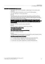
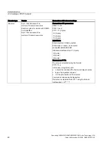
Страница 36: ...n data in the expert list as TypeOfAxis NumberOfEncoders Encoder_1 xxx The following assignments apply to the axis configuration windows Parameter Meaning Encoder type TypeOfAxis NumberOfEncoders Encoder_1 encoderType Encoder mode TypeOfAxis NumberOfEncoders Encoder_1 encoderMode Resolution TypeOfAxis NumberOfEncoders Encoder_1 IncEncoder IncResolution TypeOfAxis NumberOfEncoders Encoder_1 AbsEnco...

Страница 37: ...nnector KK120 actual position value must be set in U922 i001 actual position value encoder interface If however a multiturn encoder is used the connector KK100 absolute position must be set in U922 i001 actual position value encoder interface Parameter P183 index 1 position sensing configuration Meaning The position detection configuration is entered in this parameter The last digit enables positi...

Страница 38: ...TION Encodersystem rotatory_system Encodertype sensor_absolute absolute_cyclic EncoderMode SSI AbsEncoder Absresolution 4096 Absdatalength 24 AbsResolutionMultipliercyclic 1 AbsResolutionMultiplierabsolute 1 Endat motor encoder Endat 2048 pulses rev 1Fxxxxx xxxxx xExx Encoder system for motors with DRIVE CLiQ interface 1Fxxxxx xxxxx xFxx Masterdrives MC parameters U922 1 100 P171 22 P183 1 xxx2 SI...

Страница 39: ... rev 1Fxxxxx xxxxx xGxx Masterdrives MC parameters U922 1 100 P171 12 P183 1 xxx2 SIMOTION Encodersystem rotatory_system Encodertype sensor_absolute absolute_cyclic encoderMode ENDAT AbsEncoder Absresolution 32 Absdatalength 17 AbsResolutionMultipliercyclic 128 AbsResolutionMultiplierabsolute 4 Incremental sin cos motor encoder optical incremental encoder sin cos 1 Vpp 2048 pulses rev ERN1381 1387...

Страница 40: ...terdrives MC parameters U922 1 120 P183 1 xxx1 P171 11 2 pole 12 4 pole 13 6 pole 13 8 pole SIMOTION Encodersystem rotatory_system Encodertype sensor_incremental encoderMode RESOLVER IncEncoder IncResolution 1 2 pole 2 4 pole 4 6 pole 4 8 pole Comment on P171 The value is calculated using the formula P171 11 x In this case x log2 n 2 with x should be rounded off to the top as integer number log2 i...

Страница 41: ...ount when the cycle is resumed The encoder must be calibrated after the initial loading If the settings for the absolute encoder are modified the encoder must also be re adjusted With the CPU switched off the encoder may only be moved a maximum distance half the encoder range in both traversing directions in order to still be able to detect the exact position Finally click on Complete The set data...

Страница 42: ... the axis that was created is called and the setting Dynamic following error monitoring active is de selected under the Following error monitoring tab The following error monitoring should of course be matched to the requirements and mechanical system of the plant when commissioning an application WARNING If the following error monitoring is increased or deactivated larger incorrect movement can o...

Страница 43: ...g 4 3 Creating a STEP 7 project Connecting SIMOVERT MASTERDRIVES MC to the Technology CPU Product Information 03 2008 A5E00272072 05 43 Position controller configuration In S7T Config select the control of the axis ...

Страница 44: ...RIVES MC to the Technology CPU 44 Product Information 03 2008 A5E00272072 05 The window of the Closed loop controller is opened and the Kv factor the speed pre control and the velocity dependent interpolation are set The Dynamic Servo control DSC function remains selected ...

Страница 45: ...cifying the system clock cycles The specification of the system clock cycles in the Technology CPU affects the position reference value adaptation in MASTERDRIVES MC Technology CPU The ratio of the DP clock cycle to the position controller clock cycle and to the interpolator clock cycle diagram above is e g set to 1 2 2 This represents a DP clock cycle of 3 ms a position controller clock cycle of ...

Страница 46: ...cle and the position controller clock cycle are the same then you must enter the value 3 in P770 If the position controller clock cycle is double the DP cycle you must set the value to 4 Task monitoring time The task monitoring time monitors the processing of the Motion Control jobs Technology DB update The setting for the time of the technology DB update determines the time intervals in which the...

Страница 47: ...ted deadtimes deadtimes after the optimized DP cycle With the coupling between the control and MASTERDRIVES MC additional deadtimes occur that are dependent on the DB cycle and the firmware release of the MC In order to compensate these additional deadtimes the configuration data must be appropriately configured Using the righthand mouse key click on the axis and select Expert Expert list Figure 4...

Страница 48: ...guration data TypeofAxis SystemDeadTimeData additionalTime enter the appropriate value from the table below Figure 4 27 Input window to correct the system related deadtime DP cycle time Motion Control up to SW V2 2 Motion Control as of SW V2 2 1 5 ms 0 003 s only possible with Motion Control Performance 2 0 001875 s 2 ms 0 002 s 0 001750 s 3 ms 0 003 s 0 002625 s ...

Страница 49: ...d axis is to be referenced the referencing mode must be specified in both the Technology CPU and MASTERDRIVES MC Referencing mode External zero mark only Operational sequence When a defined edge of the external zero mark is crossed the position is accepted Hardware structure 9 0 38 7 3 352 86 3 0 67 5 5 9 6 0 52 QFRGHUV QSXW WHUPLQDO 5HIHUHQFH SRWHQWLDO WHUPLQDO Figure 4 28 Referencing External ze...

Страница 50: ...elected as the referencing mode the approach direction can be selected by means of Start search for reference Signal transition and To side of external zero mark have no significance as in motion control with the parameterization of the script file STDTLG5_T4_V21 ssc the positive signal edge is always evaluated Figure 4 29 Referencing the axis in STEP 7 referencing mode only external zero mark ...

Страница 51: ...input 4 X101 6 and measuring input 2 digital input 5 X101 7 and should be addressed via the Technology CPU Digital input 4 can be used as reference cam and as measuring input and digital input 5 can be used as measuring input The parameterization of U922 i005 and U923 i001 in Motion Control should be set to KK122 and B212 for MASTERDRIVES MC in accordance with the description below As the zero pos...

Страница 52: ...cing mode only encoder zero mark SIMOVERT MASTERDRIVES Motion Control The search for reference direction must be compatible with the parameterization of the 2nd digit of P183 i001 in the Motion Control If negative direction is selected in the window diagram above P183 i001 xx2x must be entered in the Motion Control If positive direction is selected then P183 i001 xx1x must be set in the Motion Con...

Страница 53: ...ference cam has been left the axis is referenced at the next zero mark of the encoder that is detected Hardware configuration The reference cam is connected to a free SIMATIC input either at an input integrated in the Technology CPU or at distributed input at DP DRIVE 9 0 38 7 3 352 86 3 0 67 5 5 9 6 0 52 0 QFRGHUV Figure 4 31 Referencing reference cam and encoder zero mark Technology CPU If Refer...

Страница 54: ...earch for reference in the Positive direction is selected in the window and for Encoder zero mark behind reference cam the following two diagrams then P183 i001 must be xx1x in Motion Control if Positive direction is selected and for Encoder zero mark In front of reference cam then P183 i001 must be xx2x in Motion Control The parameterization of U922 i005 and U923 i001 in Motion Control must be le...

Страница 55: ... referencing then referencing is performed using the reference point detection in the Motion Control However if only a reference cam is used for referencing the position measured value memory in Motion Control is used for referencing If reference cam and encoder zero mark or encoder zero mark only are used for referencing then connector KK124 reference point measured value should be set in U922 i0...

Страница 56: ... zero mark or encoder zero mark only are used for referencing binector B210 reference point detected acknowledgement should be set in U923 i001 reference value detected checkback signal encoder interface If however only reference cams are to be used for referencing binector B212 acknowledgement that the measured value is valid should be set in U923 i001 reference value detected checkback signal en...

Страница 57: ...tion is the acquisition of a print mark for the purpose of synchronizing the axis to this mark Hardware structure The measuring input must be connected to fast input X101 6 The input is isolated This enables more than one input to be connected in parallel whereby the reference potential of the 24V supply of the measuring input for example from the line supply must also be wired 9 0 38 7 3 352 86 3...

Страница 58: ...suring inputs can be connected to MASTERDRIVE Measuring input 1 to X101 6 Measuring input 2 to X101 7 Only one measuring input can be activated at any time Before you for example activate measuring input 2 you must ensure that measuring input 1 is not active The measuring input number should be assigned as follows Measuring input 1 measuring input number 1 Measuring input 2 measuring input number ...

Страница 59: ...4 3 Creating a STEP 7 project Connecting SIMOVERT MASTERDRIVES MC to the Technology CPU Product Information 03 2008 A5E00272072 05 59 Figure 4 36 Inserting a measuring input Figure 4 37 Measuring Input Configuration ...

Страница 60: ...signal edge at the hardware input is dependent on the configuration refer to Table 1 1 To be certain to detect the measuring edge you must ensure that MC_MeasuringInput is executed earlier by this amount of runtime in the user program When Measuring with measuring window the task is only registered in the system with MC_MeasuringInput The measuring input is only activated when the axis is at the b...

Страница 61: ...ccount Table 4 2 Measuring with measuring window Measuring edge is detected in the window MASTERDRIVES MC MC_MeasuringInput ready to evaluate the measuring range start of the measuring window 2 IS Reaching the start of the measuring window at the axis mechanical system ready to detect the measuring edge 2 IS 3 DP 2 DR Detecting the measuring edge result in the Technology CPU for further processing...

Страница 62: ...echnology Load to target system After the project has been downloaded into the target system switch the Technology CPU to RUN using the mode switch Creating the technology DBs If the configuration with S7T Config has been completed for the technology objects that have been created e g axes cams measuring inputs technology data blocks must be created To do this the Technology Objects Management too...

Страница 63: ...arts with the following dialog box Figure 4 39 Technology Objects Management The lower halves of the dialog box window show the technology objects that are either configured in S7T Config or are available as standard but for which a TO DB still does not exist If required adapt the data block numbers of the TO DBs and click on Create in order to generate the DBs Figure 4 40 Creating TO DBs ...

Страница 64: ...DTs are added Figure 4 41 TO DBs in the SIMATIC Manager 4 3 5 Activating a brake 4 3 5 1 Vertical axis application case Introduction When a braking sequential control is used in conjunction with a vertical axis the axis should remain at its position when the system is shutdown or in a fault situation The axis enable can be reset by an alarm in the technology CPU or by disabling the MC_Power functi...

Страница 65: ... enable is cancelled hence preventing the axis from sagging There are two different operating states Switch axis on off normally using MC_Power Switch off the axis in the event of axis errors with error response RELEASE_DISABLE Procedure for configuring switching the axis on off normally using MC_Power You configure an axis to switch on off normally with braking control using the stop modes on the...

Страница 66: ...2008 A5E00272072 05 Procedure for configuring the axis response to axis errors with error response RELEASE_DISABLE The response of the axis to axis errors with the RELEASE_DISABLE error response is set by changing the configuration in S7T Config Switch to the configuration dialog for the axis and click the Drive settings button ...

Страница 67: ... axis to axis errors with an error response RELEASE_DISABLE Ramp stop OFF1 Braking takes place at the drive s ramp function encoder ramp When the speed threshold is reached the holding brake is enabled which disables the pulse enable once the brake closing time has elapsed 2 6SHHG VHWSRLQW FWXDO VSHHG n ROGLQJ EUDNH 6ZLWFKLQJ 2Q QKLELWHG UDNH FORVLQJ WLPH ROGLQJ EUDNH RSHQ t t t t t ...

Страница 68: ...se the power enable is cancelled immediately and the drive costs to a standstill In parallel the mechanical braking control is enabled immediately This engages the brake which actively brakes the drive The mechanical stress on the brake depends on the load to which it is subjected 2 6SHHG VHWSRLQW FWXDO VSHHG Q Holding brake ROGLQJ EUDNH RSHQ 6ZLWFKLQJ 2Q QKLELWHG t t t t t ...

Страница 69: ...00272072 05 69 Fast stop OFF3 The drive is braked at the fast stop ramp emergency stop When the speed threshold is reached the holding brake is enabled which disables the pulse enable once the brake closing time has elapsed 6SHHG VHWSRLQW FWXDO VSHHG Q ROGLQJ EUDNH ROGLQJ EUDNH RSHQ 6ZLWFKLQJ 2Q QKLELWHG UDNH FORVLQJ WLPH 2 t t t t t ...

Страница 70: ...ntrol without checkback 2 activate braking control with checkback P606 Brake opening time P607 Brake closing time P608 Q open brake P609 Q close brake P610 Q brake threshold 1 P611 adjustable limit alarm monitor P612 Q RM brake open P613 Q RM brake closed P614 Q close holding brake P615 Q brake threshold 2 Allocating the brake activation function to the digital output You must assign the output of...

Страница 71: ...2 05 71 Example You use digital output 1 terminal X101 3 to activate the brake Connect the Open brake binary signal to the digital output by entering the binector value B0275 in parameter P651 B 0 X103 C X101 B S1 A P S 0RWRU ZLWK PRWRU KROGLQJ EUDNH 5HOD V WR FRQWURO WKH PRWRU KROGLQJ EUDNH 24 V 0 V X101 3 X101 1 X101 2 M 3 0 67 5 5 9 6 0 ...

Страница 72: ... MC using the commissioning tool is provided in the Section MASTERDRIVES MC commissioning tool Page 87 The first step in the guided commissioning procedure is to configure the hardware power unit motor encoder etc used the interfaces etc This is performed using one of the commissioning tools by calling the menu item Parameters Controlled start up Basic functions For motion control devices select t...

Страница 73: ... CPU Product Information 03 2008 A5E00272072 05 73 Select the connected motor in the 2nd window Motor Figure 4 43 Guided commissioning of the basic device 2 Motor window Select the connected motor encoder in the 3rd window Motor encoder Figure 4 44 Guided commissioning of the basic device 3 Motor encoder window ...

Страница 74: ... the 4th window Setpoints control type select PROFIBUS DP and terminal strip Figure 4 45 Guided commissioning of the basic device 4 Setpoints and control type window The optimized speed controller parameters Kp and Tn torque limits etc can be entered in the 5th window Control and window 6 Inputs outputs can be run through without making any changes with Continue ...

Страница 75: ...t Information 03 2008 A5E00272072 05 75 The PROFIBUS address is set in the 7th window Communication Figure 4 46 Guided commissioning of the basic device 7 Communication window At the end of the guided commissioning a summary of the parameterization is displayed Figure 4 47 Guided commissioning of the basic device Summary ...

Страница 76: ...with OK and Continue the parameter assignments are downloaded into the drive converter Successful loading of the parameter assignments is confirmed in the following window Figure 4 48 Message that the parameter assignments were successfully accepted The basic unit commissioning has now been completed and you can continue with connecting the MASTERDRIVES MC to the Technology CPU See also MASTERDRIV...

Страница 77: ...onnections are reset To start instructions are provided in a message box to set parameters that are dependent on the application please read these carefully that should be set in the following dialog box All of the parameters that depend on the application have already been explained in the Chapter Create a STEP 7 project Examples are parameters U922 and U923 encoder interface which have to be mod...

Страница 78: ...he sources of the digital outputs for Parameter Controlled start up Basic functions are reset at the next Execute script file You are now guided ONLINE via WINDOWS windows The script file should first be started Figure 4 49 Starting the script file STDTLG5_T4_V21 ssc After the start you must accept the liability exclusion clause and acknowledge the connection of the Motion Control to the Technolog...

Страница 79: ...alue in the dialog box for the application dependent parameter P340 pulse frequency Figure 4 51 Dialog box for setting P340 Carefully read the contents of the message box with the setting information for the application dependent parameter U922 i001 actual position value of the encoder interface and acknowledge this message Figure 4 52 Message box with setting information for U922 i001 ...

Страница 80: ...alog box for the application dependent parameter U922 i001 encoder interface position actual value Figure 4 53 Dialog box for setting U922 i001 Carefully read the contents of the message box with the setting information for the application dependent parameter U922 i005 reference value of the encoder interface and acknowledge this message Figure 4 54 Message box with setting information for U922 i0...

Страница 81: ...for the application dependent parameter U922 i005 reference value of the encoder interface Figure 4 55 Dialog box for setting U922 i005 Carefully read the contents of the message box with the setting information for the application dependent parameter U923 i001 reference point checkback signal of the encoder interface and acknowledge this message Figure 4 56 Message box with setting information fo...

Страница 82: ... the dialog box for the application dependent parameter U923 i001 reference point checkback signal of the encoder interface Figure 4 57 Dialog box for setting U923 i001 Carefully read the contents of the message box with the setting information for the application dependent parameter P171 position resolution and acknowledge the message Figure 4 58 Message box with setting information for P171 ...

Страница 83: ...solution Figure 4 59 Dialog box for setting P171 Carefully read the contents of the message box with the setting information for the application dependent parameter P183 i001 position sensing configuration and acknowledge the message Figure 4 60 Message box with setting information for P183 i001 Set the required value in the dialog box for the application dependent parameter P183 i001 position mea...

Страница 84: ...parameter P205 rated velocity and acknowledge the message Figure 4 62 Message box with setting information for P205 Set the required value in the dialog box for the application dependent parameter P205 rated velocity Figure 4 63 Dialog box for setting P205 Carefully read the contents of the message box with the setting information for the application dependent parameter P770 interpolator and ackno...

Страница 85: ...ng the script file the following message is displayed Completed or Complete Figure 4 66 Message box commissioning completed If an Error message also appears then open the associated LOG FILE it has the same name as the SCRIPT FILE but with the extension LOG either using the Log button or an editor For Drive Monitor or Drive ES you will find the LOG FILE in the same directory as the script file Not...

Страница 86: ...Commissioning 4 5 Connect MASTERDRIVES MC to the Technology CPU Connecting SIMOVERT MASTERDRIVES MC to the Technology CPU 86 Product Information 03 2008 A5E00272072 05 ...

Страница 87: ...nsert a drive using Insert Drive In the following window a MASTERDRIVES MC Plus is entered as drive type with device version 01 6 and bus address 0 or the contents of parameter P700 Then call up the overview by clicking on the drive that was entered with the righthand mouse key and the menu Target system Drive Overview and then select Tools Interface settings Under the Bus type tab select USS and ...

Страница 88: ...MASTERDRIVES MC commissioning tool Connecting SIMOVERT MASTERDRIVES MC to the Technology CPU 88 Product Information 03 2008 A5E00272072 05 ...

Отзывы: