background image

Commissioning 


7.6 Deleting data 


SIMOTION C 

156


Operating Instructions, 02/2012 

Memory reset with the mode selector 


Note 
The operation for the memory reset with the toggle switch is described below. The operation 

with the key-operated switch of the C230-2 is similar to the operation with the toggle switch. 


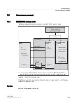
Proceed as follows (see following figure): 
1.


Set the mode selector to STOP. 

2.


Move the switch to MRES and hold the switch in this position until the STOP LED 

changes from flashing to steady illumination. 

3.


Within 3 seconds, you must release the switch and return it to the MRES position. The 

memory reset will now be performed. All the LEDs will light up during this time. The 

SIMOTION C completed the memory reset when the STOP LED lights up. 

The SIMOTION C has reset the memory. 

RQ

2II

PD[V

6723/('

$OO/('VRQ

W

05(6

6723

581

05(6

6723

581

05(6

6723

581

05(6

6723

581

05(6

6723

581

V


Figure 7-4 

Mode selector operation sequence for the memory reset 

Содержание SIMOTION C

Страница 1: ... ___________________ ___________________ SIMOTION SIMOTION C Operating Instructions Valid for SIMOTION C230 2 C240 and C240 PN 02 2012 Preface Description 1 Operator control hardware 2 Interfaces 3 Configuring and installing 4 Connecting 5 Addressing 6 Commissioning 7 Maintenance and servicing 8 Alarm error and system messages 9 Technical data 10 Dimension drawing spare parts and accessories 11 St...

Страница 2: ...fic task in accordance with the relevant documentation in particular its warning notices and safety instructions Qualified personnel are those who based on their training and experience are capable of identifying risks and avoiding potential hazards when working with these products systems Proper use of Siemens products Note the following WARNING Siemens products may only be used for the applicati...

Страница 3: ... the mechanical design and how to install the SIMOTION C components Connecting This section describes the wiring and networking of SIMOTION C Addressing This section contains the information you will require to define the module start addresses for the modules you are using Commissioning hardware This section describes how you commission the hardware components and what you must take into account ...

Страница 4: ...standards in the appendix The current Declaration of Conformity is on the Internet at http support automation siemens com WW view de 15257461 SIMOTION Documentation An overview of the SIMOTION documentation can be found in a separate list of references This documentation is included as electronic documentation in the scope of delivery of SIMOTION SCOUT It comprises 10 documentation packages The fo...

Страница 5: ...g link for information on how to compile documentation individually on the basis of Siemens content and how to adapt this for the purpose of your own machine documentation http www siemens com mdm Training Click the following link for information on SITRAIN Siemens training courses for automation products systems and solutions http www siemens com sitrain FAQs Frequently Asked Questions can be fou...

Страница 6: ... contain halogens Marking of the plastic materials as per ISO 11469 Less material used because the unit is smaller and with fewer components thanks to integration in ASICs The product is to be disposed of in accordance with national regulations The product described in this manual can be recycled owing to its low pollutant content To recycle and dispose of your old device in an environmentally fri...

Страница 7: ... interface 36 3 3 PROFINET interface C240 PN 39 3 4 PROFIBUS DP interfaces 42 3 5 Onboard drive interface C230 2 C240 45 3 6 Onboard measuring system interface C230 2 C240 52 3 7 Possible uses of onboard drive and measuring system interface in the application C230 2 C240 63 3 7 1 Overview 63 3 7 2 Configuration examples for C240 65 3 8 I O interface 68 4 Configuring and installing 77 4 1 General r...

Страница 8: ...PROFINET interface C240 PN 129 5 2 6 Factory setting 131 5 2 7 MPI subnet 131 6 Addressing 133 6 1 Slot oriented address allocation for modules default addresses for centralized I O 133 6 2 User assignable addressing on the SIMOTION C centralized and distributed I O 135 6 3 Addressing signal modules 136 6 4 Addressing the onboard digital inputs and outputs of the SIMOTION C 139 6 5 Addressing the ...

Страница 9: ...al data 171 10 2 Real time clock 179 10 3 Transportation and storage conditions for SIMOTION C 179 10 4 Mechanical and climatic environmental conditions for operation of the SIMOTION C 180 10 5 Specifications for dielectric tests safety class and degree of protection 182 11 Dimension drawing spare parts and accessories 183 11 1 Dimension drawing 183 11 2 Spare parts and accessories 184 A Standards...

Страница 10: ...Table of contents SIMOTION C 10 Operating Instructions 02 2012 ...

Страница 11: ...ve The SIMOTION C is a motion control module for the control of servo drives As of V3 2 stepper drives with a pulse direction interface can be connected to the onboard drive interfaces The following configurations can be selected C230 2 and C240 Up to four axes via the onboard drive interface or C230 2 C240 and C240 PN Axes via PROFIBUS DP or C240 PN Axes via PROFINET IO or Mixed operation with a ...

Страница 12: ...e System integration SIMOTION offers an optimized system platform for automation and drive solutions where priority is given to motion control applications and technological tasks The SIMOTION modular system consists of the SIMOTION SCOUT engineering system and a common runtime system for various hardware platforms The truly innovative aspect of SIMOTION is that it does away with the traditional s...

Страница 13: ...hnology functions This approach enables the motion control of axes and machine control within the same system The same applies to technology functions such as pressure control of a hydraulic axis A seamless switch can be made from position controlled positioning mode to pressure control Combining the three open loop control functions of motion control PLC and technology functions has the following...

Страница 14: ...ting Instructions 02 2012 The following figures show system configurations with SIMOTION C230 2 C240 and C240 PN 6 0 7 0 GHYLFH 352 86 3 352 86 3 LVRFKURQRXV HTXLGLVWDQW 36 3 3 WKHUQHW 6 2 2QERDUG GULYH LQWHUIDFH 6 7 7 Figure 1 2 System overview of C240 ...

Страница 15: ... 3 WKHUQHW 6 2 352 1 7 2 6 0 7 6 1 0 6 6 1 0 6 6 1 0 6 6 7 7 7 6 1 0 6 6 Figure 1 3 System overview of C240 PN Components The most important components of a SIMOTION application with SIMOTION C and their functions are listed below Note The modules and devices approved for the SIMOTION C are listed in the SIMOTION PM 21 Catalog This document is supplied in electronic format with SIMOTION SCOUT ...

Страница 16: ... the analog interfaces can also be used as available process outputs Incremental encoders or absolute encoders can be connected to the measuring system interface C230 2 C240 With the C240 free remaining encoder inputs of an axis channel can be used as the input for a 16 bit up down counter Power supply PS converts the line voltage 120 230 V AC into an operating voltage of 24 V DC to supply the SIM...

Страница 17: ...ATIC S7 controllers with PROFINET IO interface SIMATIC ET 200 I O systems with PROFINET IO interface Drive units Other SIMOTION controllers Note All approved devices are listed in the PM 21 Catalog and in chapter I O modules approved for SIMOTION Page 18 Table 1 3 Further components that can be connected to the SIMOTION C Component Function Programming device PG PC configures parameterizes program...

Страница 18: ...ction for machine level use without a control cabinet with new features such as small frame size integrated PROFIsafe safety technology PROFINET connection and hot swapping of modules Other PROFIBUS DP I O ADI 4 Analog Drive Interface For the connection of drives with analog 10 V setpoint interface IM174 interface module for 4 axes For the connection of drives with analog 10 V setpoint interface e...

Страница 19: ...hronous data traffic DP V2 These modules are integrated via the GSD file from the device manufacturer Note Please note that in individual cases further boundary conditions must be fulfilled in order to integrate a standard slave into SIMOTION Some modules need driver blocks e g in the form of function blocks which make integration possible or much easier For modules approved for use with SIMOTION ...

Страница 20: ...HU 0 a Figure 1 4 Servo system with converter e g SIMODRIVE 611 universal with built in incremental encoder Incremental encoder C230 2 C240 For position measurement the encoders usually connected supply counting pulses according to their resolution for the distances traveled These can be rotary encoders or linear scales Homing is necessary to determine the absolute position reference Absolute enco...

Страница 21: ...in this case 3RVLWLRQ FRQWUROOHU 6SHHG VHWSRLQW 3RZHU XQLW XUUHQW FRQWUROOHU 6SHHG FRQWUROOHU 6HUYR PRWRU 5RWRU SRVLWLRQ QFRGHU RQYHUWHU UHOHDVH FWXDO SRVLWLRQ YDOXH HUR PDUN 0 a Figure 1 5 Servo system with converter e g SIMODRIVE 611 universal with incremental encoder Position controlled motion control for servo axes PROFIBUS DP SIMOTION C enables position controlled motion control of axes via P...

Страница 22: ...ue With this type of control circuit the motor cannot lose any steps in order to enable exact positioning 3RVLWLRQ FRQWUROOHU FOH FORFN GLUHFWLRQ UHOHDVH RQWURO 3RZHU XQLW 60 3XOVH HQFRGHU 5LQJ FRXQWHU 3KDVH FXUUHQW FRQWUROOHU WHUQDO HUR SXOVH 5RWDWLRQ PRQLWRULQJ 6 0267 3 Figure 1 7 Controlled stepper motor system with control circuit Position controlled stepper motor control C230 2 C240 The C230 ...

Страница 23: ...OFINET IO The C240 PN enables position controlled motion control of axes via PROFINET IO 31 3RVLWLRQ FRQWUROOHU 6SHHG VHWSRLQW 3RZHU XQLW XUUHQW FRQWUROOHU 6SHHG FRQWUROOHU 6HUYR PRWRU FWXDO VSHHG YDOXH QFRGHU FWXDO SRVLWLRQ YDOXH HUR PDUN RQYHUWHU FWXDO SRVLWLRQ YDOXH 352 1 7 2 0 a 3 3 3 Figure 1 9 Servo system with converter e g SINAMICS S120 with CBE20 ...

Страница 24: ...G VWDWXV GLVSOD V ULYH LQWHUIDFH 0RGH VHOHFWRU VZLWFK RQQHFWLRQ IRU SRZHU VXSSO 2 LQWHUIDFH URQW FRQQHFWRU WKHUQHW LQWHUIDFH 0HPRU PRGXOH VORW IRU PLFUR PHPRU FDUG 352 86 3 LQWHUIDFH 6WDWXV GLVSOD V LJLWDO LQSXWV RXWSXWV 352 86 3 03 LQWHUIDFH WKHUQHW 0 DGGUHVV QVFULSWLRQ ODEHOV URQW GRRU KLQJHG XV FRQQHFWRU IRU 2 EXV 0RXQWLQJ UDLO 7 SH SODWH 0LFUR 0HPRU DUG 00 MHFWRU IRU PLFUR PHPRU FDUG 6 9 581 6...

Страница 25: ...VSOD V ULYH LQWHUIDFH 0RGH VHOHFWRU VZLWFK RQQHFWLRQ IRU SRZHU VXSSO 2 LQWHUIDFH URQW FRQQHFWRU WKHUQHW LQWHUIDFH 0HPRU PRGXOH VORW IRU PLFUR PHPRU FDUG 352 86 3 LQWHUIDFH 6WDWXV GLVSOD V LJLWDO LQSXWV RXWSXWV 352 86 3 03 LQWHUIDFH WKHUQHW 0 DGGUHVV QVFULSWLRQ ODEHOV URQW GRRU KLQJHG XV FRQQHFWRU IRU 2 EXV 0RXQWLQJ UDLO 7 SH SODWH 0LFUR 0HPRU DUG 00 MHFWRU IRU PLFUR PHPRU FDUG 6 9 581 67238 6723 8...

Страница 26: ...FWLRQ IRU SRZHU VXSSO 2 LQWHUIDFH URQW FRQQHFWRU WKHUQHW LQWHUIDFH 0HPRU PRGXOH VORW IRU PLFUR PHPRU FDUG 352 86 3 LQWHUIDFH 6WDWXV GLVSOD V LJLWDO LQSXWV RXWSXWV 352 86 3 03 LQWHUIDFH WKHUQHW 0 DGGUHVV LDJ QR IXQFWLRQ 352 1 7 SRUW 7 51 7 SRUW QVFULSWLRQ ODEHOV URQW GRRU KLQJHG XV FRQQHFWRU IRU 2 EXV 0RXQWLQJ UDLO 7 SH SODWH 0LFUR 0HPRU DUG 00 MHFWRU IRU PLFUR PHPRU FDUG 3 3 3 8 6 1 8 7 FWLYLW HOO...

Страница 27: ...n the current module may differ from those described in this manual e g updated product status approvals and markings not yet issued etc 0RGXOH GHVLJQDWLRQ 3URGXFW YHUVLRQ 2UGHU QXPEHU RQQHFWLRQ SDUDPHWHUV 6HULDO QXPEHU DUFRGH 0 QR 3 8 DUFRGH 3URGXFW 1R DUFRGH VHULDO QR 67 3 DUFRGH 0 DGGUHVV DUFRGH YHUVLRQ 0 DGGUHVV 1 217 4 5 8 3 9HUV 1387 9 SIEMENS 6 027 21 6 21752 2 9 9 0DGH LQ HUPDQ 6 7 3 1 Fig...

Страница 28: ...HUVLRQ DU FRGH 0 DGGUHVV 0RGXOH GHVLJQDWLRQ 2UGHU QR RQQHFWLRQ SDUDPHWHU IND CONT EQ 58RA Figure 1 14 Type plate of the C240 DU FRGH 0 QR DU FRGH SURGXFW QR DU FRGH VHULDO QR DU FRGH YHUVLRQ DU FRGH 0 DGGUHVV DU FRGH 0 DGGUHVV 31 0RGXOH GHVLJQDWLRQ 9HUVLRQ 2UGHU QR RQQHFWLRQ SDUDPHWHU 6HULDO QXPEHU VW 0 DGGUHVV 31 0 DGGUHVV Figure 1 15 Type plate of the C240 PN ...

Страница 29: ... 1AA00 0AA0 6AU1 240 1AB00 0AA0 6AU1 700 0AA02 0AA0 6AU1 720 1KA00 0AA0 Note The MMC of the C240 and the C240 PN are identical Order number of the Micro Memory Card MMC Note The MMC of the C240 C240 PN cannot be operated in the C230 2 and vice versa Uses of the analog drive interface X2 For analog drives For stepper drives For analog drives For stepper drives For standard outputs analog digital ou...

Страница 30: ...sitions RUN STOP MRES Toggle switch Switch positions RUN STOP MRES PROFINET interface X11 Not available Not available 3x PROFINET X11 P1 X11 P2 X11 P3 Note In order to take the different versions into account the product will be referred to in this manual as SIMOTION C Specific product designations will be used for information that applies only to one product version e g for SIMOTION C230 2 C240 o...

Страница 31: ...process image of outputs The technology packages are active in this state They can execute commands from the user program Note With the C230 2 the key cannot be removed in this position STOPU SIMOTION C does not execute a user program The technology packages are active Test and commissioning functions can be executed The user program is not active The I O modules SMs are in a safe state With the C...

Страница 32: ...tor requires a specific sequence of operation see chapter SIMOTION C memory reset Page 154 2 1 2 Micro Memory Card MMC SIMOTION C230 2 micro memory card The following micro memory card is available Order no 6AU1 700 0AA02 0AA0 The micro memory card for SIMOTION C230 2 can be used to save the SIMOTION Kernel in order to run an update See chapter SIMOTION kernel update Page 159 The SIMOTION Kernel s...

Страница 33: ...t is not supplied with the SIMOTION C240 C240 PN and must be ordered as a separate component Note The SIMOTION C240 C240 PN does not contain any firmware The micro memory card for the SIMOTION C240 C240 PN can be used to save the SIMOTION Kernel The micro memory card is also needed to save the technology packages and user data programs configuration data parameterizations CAUTION The micro memory ...

Страница 34: ...the SIMOTION C PROFIBUS DP1 interface X8 BUS2F red Group fault This LED indicates a fault on the SIMOTION C PROFIBUS DP2 MPI interface X9 Q0 to Q7 I0 to I11 B1 to B4 M1 M2 green Digital inputs digital outputs These LEDs show the status of the digital inputs outputs The following LED displays are arranged the front cover of the SIMOTION C240 PN This table describes the LEDs and their function Table...

Страница 35: ...he fast digital inputs digital outputs including measuring inputs and external zero mark and for wiring the READY relay Power supply connection 4 pin screw type terminal connection X10 for connecting the 24 V load power supply Memory module slot Slot for micro memory card MMC PROFIBUS DP1 interface 9 pin Sub D socket X8 for connection to the PROFIBUS DP This interface can be used for isochronous o...

Страница 36: ...HMI Communication between SIMOTION and SIMATIC NET OPC The SIMATIC NET SOFTNET S7 S7 OPC server software must be installed on the PG PC for this function Note SOFTNET S7 is a superset of SOFTNET PG i e SOFTNET S7 contains Protocol TPC IP RFC 1006 as well For more information about the software packages see SIMOTION Motion Control System PM 21 Catalog This documentation is supplied in electronic fo...

Страница 37: ... DGGUHVV H J 05 6 6723 581 3 03 3 6 0 16 Figure 3 1 X7 interface position C230 2 C240 31 3 3 3 8 6 1 8 7 WKHUQHW 0 DGGUHVV 3URILQHW 2 0 DGGUHVV 3 03 3 31 6 0 16 581 6723 05 6 Figure 3 2 X7 interface position C240 PN Interface assignment Designation X7 Ethernet Type 8 pin RJ45 socket Table 3 2 X7 interface assignment Pin Name Type Pin Name Type 1 TDP O 5 Not assigned 2 TDM O 6 RDM I 3 RDP I 7 Not a...

Страница 38: ...N C 38 Operating Instructions 02 2012 Signal names RDP RDM Receive Data TDP TDM Transmit Data Signal type I signal input O signal output Note You will find additional information about Ethernet in the SIMOTION SCOUT Communication System Manual ...

Страница 39: ...communication The data traffic is further optimized and accelerated through an additional topology planning The high performance option always requires a configuration of the topology With the aid of IRT high performance IO devices I O modules and drive units that support IRT can be operated isochronously on PROFINET IO and data can be exchanged between the SIMOTION devices via the controller cont...

Страница 40: ...ote All released modules and devices are listed in the PM 21 Catalog and in chapter I O modules approved for SIMOTION Page 18 This documentation is supplied in electronic format with SIMOTION SCOUT Take note of the documentation on the individual modules or devices Interface position The following figure shows the mounting position and the designation of the PROFINET IO interface on the module 3 0...

Страница 41: ...t Table 3 3 X11 interface assignment ports P1 P2 P3 Pin Name Type Pin Name Type 1 TDP O 5 Not assigned 2 TDM O 6 RDM I 3 RDP I 7 Not assigned 4 Not assigned 8 Not assigned Signal names RDP RDM Receive Data TDP TDM Transmit Data Signal type I signal input O signal output Note You will find additional information about PROFINET in the SIMOTION SCOUT Communication System Manual ...

Страница 42: ...he following devices can be connected to the PROFIBUS DP interfaces PG PC SIMATIC HMI devices SIMATIC S7 controllers with PROFIBUS DP interface Distributed I O e g SIMATIC ET 200M The digital inputs digital outputs are updated in the position control cycle clock SIMOTION controller Teleservice adapter Drive units with PROFIBUS DP interface e g SIMODRIVE 611 universal according to PROFIdrive profil...

Страница 43: ...e designation of the interfaces on the module 3 03 3 6 0 16 3 3 03 05 6 6723 581 Figure 3 4 Position of connectors X8 X9 Interface assignments Designation X8 X9 DP1 DP2 MPI Type 9 pin Sub D socket connector Table 3 4 X8 X9 interface assignments Pin Name Type Pin Name Type 1 Not assigned 6 P5 VO 2 M24 VO 7 P24 VO 3 B I O 8 A I O 4 RTS O 9 Not assigned 5 M5 VO ...

Страница 44: ...nal names Signal name Meaning A B Data input output RS485 RTS Transmission request P5 5 V power supply 60 mA short circuit proof M5 5 V reference potential P24 24 V supply 150 mA short circuit proof not isolated M24 24 V reference potential Signal type O signal output I O signal input output VO voltage output ...

Страница 45: ... be connected to the 50 pin Sub D socket X2 Any hybrid configuration can be used for up to four drives In addition the C230 2 and C240 provide one enable signal per axis With the C240 this interface X2 can also be used for standard outputs 4 analog outputs 4 digital outputs Position of the connector The following figure shows the installation position and the designation of the connector on the mo...

Страница 46: ... O 42 PULSE3_N O 10 DIR3 O 27 ENABLE3_N O 43 DIR3_N O 11 PULSE4_N O 28 ENABLE4 O 44 PULSE4 O 12 DIR4_N O 29 ENABLE4_N O 45 DIR4 O 13 Not assigned 30 Not assigned 46 Not assigned 14 CTREN1 1 C 31 Not assigned 47 CTREN1 2 C 15 CTREN2 1 C 32 Not assigned 48 CTREN2 2 C 16 CTREN3 1 C 33 Not assigned 49 CTREN3 2 C 17 CTREN4 1 C 50 CTREN4 2 C Signal names Table 3 7 Signal names for drives with analog int...

Страница 47: ...or the setpoint signal connected internally to logic ground Controller enable CTREN Contact assembly mated set NO contact used for axis specific enabling of the drive e g a SIMODRIVE drive unit The RF signal to the drive is set as soon as the controller enable is signaled by the user program Note When used as a digital output the contact must be supplied with voltage WARNING Brief voltage peaks ma...

Страница 48: ...roller and the actual position Direction signal DIR The output signal level determines the direction of rotation of the motor Signal ON Rotation to the left Signal OFF Rotation to the right Note If the direction of rotation of the motor is different you can change the direction of rotation by means of the Reversal of traversing direction configuration data element Refer to the technical documentat...

Страница 49: ...ssion An asymmetrical transmission is also possible however the maximum cable length in this case is limited to 10 m Note Because of the wide range of non standardized input circuits of the drive units during asymmetrical transmission no responsibility can be taken for this function In particular cable lengths and the limit frequency depend on the properties of the input circuit and the cable bein...

Страница 50: ...ive signal circuits 6 PPHWULF WUDQVPLVVLRQ ZLWK GLIIHUHQWLDO LQSXW DFFRUGLQJ WR 56 ื P 5 ื P ื P ื P 6 PPHWULFDO WUDQVPLVVLRQ ZLWK RSWRFRXSOHU LQSXW V PPHWULFDO WUDQVPLVVLRQ ZLWK RSWRFRXSOHU LQSXW V PPHWULFDO WUDQVPLVVLRQ ZLWK YROWDJH LQSXW 92 92 92 1 2 1 1 1 1 ULYH XQLW 6 027 21 Figure 3 6 Possible protective signal circuits for the stepper motor interface ...

Страница 51: ...are used actuating signal for axis of analog output Output values are interpolated linearly via the servo cycle clock Procedure 1 Select the C240 in the rack 2 Select the menu command Edit Object Properties to open the Properties C240 R0 S2 dialog 3 You can set the filter time in the Onboard I O tab The controller enable contacts connector X2 CTREN1 to 4 can also be used on the C240 as four digita...

Страница 52: ...der A 15 pin Sub D socket for the connection of incremental or absolute encoders SSI is provided for each axis With the C240 this interface X3 to X6 can also be used as a counter input Position of connectors This figure shows the mounting position and the designation of the connector on the module 1 2 5 1 2 5 3 03 3 6 0 16 05 6 6723 581 Figure 3 8 Position of connectors X3 to X6 ...

Страница 53: ...LS O 10 Z I 3 CLS_N O 11 Z_N I 4 P5EXT VO 12 B_N I 5 P24EXT VO 13 B I 6 P5EXT VO 14 A_N DATA_N I 7 MEXT VO 15 A DATA I 8 Not assigned Signal names Table 3 10 Measuring system interface signal names Signal name Meaning A A_N Track A non inverted and inverted incremental encoder B B_N Track B non inverted and inverted incremental encoder Z Z_N Zero mark non inverted and inverted incremental encoder ...

Страница 54: ...5 V encoder power supply and TTL RS422 interface Incremental encoders with 24 V encoder power supply and TTL RS422 interface Absolute encoders single multi turn with 24 V encoder power supply and SSI interface Shaft position encoders with 5 V encoder power supply and TTL RS422 interface Rotor position encoder with SINE signals Resolver Direct Direct Direct Direct Via SIMODRIVE drive control using ...

Страница 55: ...lease note the drive manufacturer s wiring specifications As the encoder interface of the C230 2 C240 is non isolated it may be necessary to take special measures for EMC on a case by case basis Encoder properties Incremental encoder Table 3 12 Incremental encoder properties Property Condition Transmission procedure Differential transmission using 5 V rectangular signals as in RS422 standard Track...

Страница 56: ...encoders RXQW SXOVH ZLWK SXOVH TXDGUXSOLFDWLRQ ุ QV ุ QV ุ QV B1 B1 B1 Figure 3 9 Signal forms of incremental encoders Note If you want to connect incremental encoders without zero signals then you must connect the corresponding pins in the connector with the encoder power supply Pin 10 with Pin 7 or 9 MEXT Pin 11 with Pin 4 or 6 P5EXT ...

Страница 57: ...eters of the SSI encoder Encoders which transmit a greater number of data bits than are to be read in the set SIMOTION C message length cannot be connected The configuration data can be set within the range of the maximum values specified in the following message profiles fir tree or right justified Fir tree profile The encoder always transmits the number of revolutions with the first 12 cycles Th...

Страница 58: ... RI LQFUHPHQWV 6XEVHTXHQW HURV RI HQFRGHU Figure 3 10 Fir tree profile Note Please note the following Bit 20 of the number of revolutions is fixed on the 12th cycle followed on the 13th cycle by the most significant bit of the number of increments revolution The leading and subsequent data bits transmitted by the encoder or zeros are not evaluated by SIMOTION C The encoder used in the example shou...

Страница 59: ...tted by the encoder with the first cycle The configured data width is monitored by the encoder driver depending on the configured message length The maximum encoder pulses per revolution is monitored depending on the data width configured Configuration data Message length 13 21 25 cycles can be selected Encoder pulses per revolution 2 Data width Data width message length ...

Страница 60: ...Operating Instructions 02 2012 0D LPXP GDWD ZLGWK RU F FOH FORFNV RU F FOH FORFNV RU F FOH FORFNV 0D LPXP HQFRGHU SXOVHV SHU UHYROXWLRQ 335 DPSOH ELW VLQJOH WXUQ HQFRGHU GDWD ZLGWK ELWV 0LQLPXP PHVVDJH OHQJWK 7RWDO YDOXH UDQJH RI WKH HQFRGHU Figure 3 11 Right justified profile ...

Страница 61: ...the connecting cable without the need for additional wiring The voltage supplied is protected electronically against short circuits and thermal overload and it is monitored The encoder supply is not isolated from the load power supply to the module Encoder supply 24 V For encoders with an operating voltage of 24 V the 24 VDC power is supplied to the Sub D sockets This means you can supply the enco...

Страница 62: ...e encoder The maximum cable length depends on the specification for the encoder supply and the baud rate For problem free operation you must not exceed the following values when using SIEMENS preassembled connecting cables see Catalogs PM 21 NC 60 ST 70 Table 3 14 Maximum cable lengths depending on the encoder power supply Supply voltage Encoder supply voltage range Current consumption Max cable l...

Страница 63: ...the C230 2 C240 Table 3 16 Combination possibilities for the C230 2 C240 Axis channel Application Output X2 Input X3 to X6 Position axis x x Drive axis x External encoder x Also for C240 Standard output I O variables Analog output PQW Digital output PQ x x Standard input I O variables 1 Counter input PIW x 1 The incremental encoder used must not have a zero pulse Note A standard output and a drive...

Страница 64: ...e of unassigned axis channels of the C240 as I O variable for the user program Use of the analog outputs of the C240 as unassigned process outputs Note The resolution and the characteristic curve of the analog output of the C240 differ from those of a SIMATIC S7 controller The following table lists the digital values and their associated analog values characteristic curve Digital value WORD data t...

Страница 65: ...on C230 2 C240 SIMOTION C Operating Instructions 02 2012 65 3 7 2 Configuration examples for C240 Use as standard output on X2 Configuration procedure in SIMOTION SCOUT 1 Start address is specified in the hardware configuration 2 Specification of standard output 16 bit analog and 1 bit digital ...

Страница 66: ... channel e g for a speed controlled axis can be used as an input for a 16 bit up down counter 90 degree pulse train of a connected TTL encoder zero pulse not required The counter value can be accessed by means of an I O variable Configuration procedure in SIMOTION SCOUT 1 Specification of start address in the hardware configuration 2 Use of the available encoder input as an additional counter usin...

Страница 67: ...terface in the application C230 2 C240 SIMOTION C Operating Instructions 02 2012 67 Note Use of the drive and encoder interfaces as standard outputs and counter inputs is only possible via their direct I O address Symbolic assignment is not available for this application ...

Страница 68: ...ncoders and actuators can be connected via digital inputs and outputs to the 40 pin front connector X1 with single wire connection Position of the connector The following figure shows the position of the front connector DEHOLQJ RI LQQHU GRRU URQW FRQQHFWRU LQ ZLULQJ SRVLWLRQ 0 0 5 Figure 3 13 Position of connector X1 ...

Страница 69: ...d block diagram The following figure shows the terminal diagram and block diagram for digital inputs outputs on the SIMOTION C 6WDWXV GLVSOD V QWHUQDO EDVLF FLUFXLW 6 027 21 JUHHQ 9 0 0 9 0LQSXW 0RXWSXW 0 0 0 0 Figure 3 14 Terminal and block diagram of digital inputs outputs on the SIMOTION C ...

Страница 70: ... Pin Name Type Pin Name Type 1 L VI 21 Unassigned 2 Q0 DO 22 B1 DI 3 Unassigned 23 B2 DI 4 Q1 DO 24 B3 DI 5 Unassigned 25 B4 DI 6 Q2 DO 26 M1 DI 7 Unassigned 27 M2 DI 8 Q3 DO 28 I0 DI 9 Unassigned 29 I1 DI 10 RDY 1 C 30 I2 DI 11 RDY 2 C 31 I3 DI 12 Unassigned 32 I4 DI 13 Q4 DO 33 I5 DI 14 Unassigned 34 I6 DI 15 Q5 DO 35 I7 DI 16 Unassigned 36 I8 DI 17 Q6 DO 37 I9 DI 18 Unassigned 38 I10 DI 19 Q7 D...

Страница 71: ... and M2 I0 to I11 Digital inputs 0 to 11 Q0 to Q7 Digital outputs 0 to 7 L Supply for digital outputs Moutput Reference potential for digital outputs Minput Reference potential for digital inputs Signal type DI digital input 24 V signal DO digital output 24 V signal K switching contact VI voltage input DANGER The 24 V power supply is to be designed as functional extra low voltage with protective s...

Страница 72: ...es for local measuring M1 M2 With a signal edge at the relevant input the current actual values of one or more encoders connected to X3 to X6 are measured with positioning accuracy to determine lengths or distances The assignment of inputs is not fixed the special use is activated in the SCOUT engineering system during configuration of the Measuring Input TO via the measuring input number C230 2 C...

Страница 73: ...SCOUT engineering system during configuration of the Measuring Input TO see the configuration example below for global measuring Up to two edges can be measured for each position control cycle clock of the Measuring Input TO The measured values must be read from the user program before they can be overwritten by a new measurement Global measuring can be used for the following applications Several ...

Страница 74: ...tatus change in Messtaster actualInputState POSITIVE NEGATIVE or vice versa When the measurement result is received the measurement position is stored Once the measurement has been taken the state variable is set to TRIGGER_OCCURRED and the measured values can be evaluated using the measuredValue1 and measuredValue2 variables for two measured edges The counterMeasuredValue1 and counterMeasuredValu...

Страница 75: ... With a signal edge at the measurement input the current actual value of the assigned encoder is recorded with an exact position Digital outputs onboard Eight digital outputs Q0 to Q7 are provided on the SIMOTION C These can also be interconnected via symbolic assignment using variables as of SIMOTION V4 2 for C240 and C240 PN These fast outputs onboard can be used as freely addressable process ou...

Страница 76: ... operating states with an open or closed READY contact Table 3 19 Statuses of enable signals and outputs Status of the READY contact SIMOTION C Status of enable signals and outputs Open During ramp up During memory reset With fault condition In STOP mode In STOPU mode Controller enable deactivated Analog outputs at 0 V Digital outputs deactivated Closed in RUN mode Enable signals and outputs contr...

Страница 77: ...g the installation of SIMOTION C modules you must pay attention to the electrical configuration Therefore also refer to the chapter Wiring Page 91 Open equipment These modules are open equipment This means they may only be installed in housings cabinets or in electrical service rooms that can be entered or accessed exclusively by means of a key or tool Housings cabinets or electrical service rooms...

Страница 78: ...d vertical configuration Design You can install the rack either horizontally or vertically The horizontal configuration should be used if possible Permissible ambient temperature Horizontal installation 0 C to 55 C Vertical installation 0 C to 40 C RUL RQWDO PRXQWLQJ 9HUWLFDO DUUDQJHPHQW 6 027 21 DQG WKH SRZHU VXSSO DUH DOZD V DUUDQJHG WR WKH OHIW RU EHORZ Figure 4 1 Horizontal and vertical config...

Страница 79: ...de space to lay wiring Increase the mounting height of the rack to 205 mm To guarantee the functionality clearances of 40 mm must be maintained Note If you use a shield connecting element the dimensions stated are measured from the lower edge of the shield connecting element Clearances The following figure shows the clearances between the individual racks and the clearance to adjacent equipment ca...

Страница 80: ...m 200 mm SIMOTION C 200 mm Signal modules SMs 40 mm Function modules FM 40 mm or 80 mm Communications processors CP 40 mm 125 mm 185 mm with shield connecting element 130 mm or 180 mm with an open front cover of the SIMOTION C Mounting rail lengths Depending on the configuration you have chosen you can use the following mounting rails Table 4 2 Mounting rails Mounting rail Usable length for module...

Страница 81: ...mation Systems M7 300 Module Data Manual The total power consumption from the backplane bus of all modules that are mounted on a rack must not exceed 1 2 A This figure shows the order of the modules in an installation with eight I O modules 2 PRGXOHV 36 6 027 21 Figure 4 3 Layout of modules on a rack Installation of FM STEPDRIVE The FM STEPDRIVE modules can be installed in addition to the eight SM...

Страница 82: ...65 interface modules have a fixed connection via a 1 meter long connecting cable The total power consumption of the inserted I O modules of both racks must not exceed 1 2 A the power consumption from rack 1 is limited to 800 mA Rules The following rules apply with respect to the layout of the modules on two racks The interface module always occupies Slot 3 and is always left of the first signal mo...

Страница 83: ...ation using SIMOTION C modules SIMOTION C Operating Instructions 02 2012 83 2 tier layout The figure below shows the 2 tier layout with SIMOTION C 2 PRGXOHV 5DFN 5DFN RQQHFWLQJ FDEOH 2 PRGXOHV 36 6 027 21 0 6 0 5 Figure 4 4 Layout of modules on two racks ...

Страница 84: ...onger than 830 mm If so you must drill additional holes for more mounting screws to stabilize the mounting rail Mark out these holes along the groove in the middle section of the rail see the figure below These additional holes should be spaced approximately every 500 mm If not no additional work required 4 Drill the 6 5 0 2mm diameter holes where marked for M6 size screws 5 Fit an M6 screw to sec...

Страница 85: ...m 10 mm 140 mm 482 6 mm 8 3 mm 466 mm 530 mm 15 mm 500 mm 830 mm 15 mm 800 mm Mounting screws Choose one of the following types of screw to mount the mounting rail Table 4 5 Mounting screws For you can use Explanation M6 cylinder head screw per ISO 1207 ISO 1580 DIN 84 DIN 85 Outer mounting screws M6 hexagonal screw per ISO 4017 DIN 4017 Additional mounting screw 2 meter mounting rail only M6 cyli...

Страница 86: ...ction between the mounting rail and the substrate Use suitable electro lubricant or contact washers with painted and anodized metals for example If not no special action required 3 Connect the mounting rail with the protective conductor An M6 protective conductor screw is provided on the mounting rail for this purpose Minimum cross section of protective conductor line 10 mm2 Note Always make sure ...

Страница 87: ...cal connections between the modules One labeling plate To label the inputs and outputs on the module Sequence in which modules are affixed to the mounting rail 1 Power supply module 2 SIMOTION C 3 Signal module s Installation sequence The individual steps for the installation of the modules are described below 1 Except for the SIMOTION C each signal module is supplied with a bus connector When plu...

Страница 88: ... the C230 2 Assigning the slot numbers After mounting you can assign each module a slot number This eases the assignment of the modules to the configuration table in the Engineering System The table below shows the slot number assignment Table 4 7 Slot numbers for S7 modules and SIMOTION C Slot no Module Comments 1 Power supply PS 2 SIMOTION C 3 Reserved 4 1 I O module To the right of SIMOTION C 5...

Страница 89: ...ing SIMOTION C Operating Instructions 02 2012 89 Inserting slot numbers This figure shows the proper way of inserting the slot numbers The slot number labels are included with the SIMOTION C Figure 4 8 Inserting slot numbers on the modules ...

Страница 90: ...Configuring and installing 4 3 Installing SIMOTION C 90 Operating Instructions 02 2012 ...

Страница 91: ...hes Equipment and measures for protection of motors and power electronics in accordance with the installation guidelines of the used drive units In addition in order to identify hazards we recommend that a risk analysis be conducted on the entire system in accordance with the basic safety requirements set out in Appendix 1 of EU Machinery Directive 89 392 EEC Additional references Please also note...

Страница 92: ... identifies the considerations required for the supply voltage Table 5 2 Supply voltage Scope Requirement Stationary systems without all pole power disconnect switches A power disconnect switch or a fuse must be provided in the electrical installation for the building Load power supply power supply modules The set rated voltage range corresponds to the local supply voltage All electric circuits Th...

Страница 93: ... must not exceed 1 2 A This is the current that the SIMOTION C can supply on the I O bus PS 307 power supply modules are available for different loads 2 A 5 A 10 A The selection of the appropriate power supply depends on the sum of the current consumption of the SIMOTION C the connected I O modules and any other connected loads fed by the load power supply The power loss of all components used in ...

Страница 94: ...QSXWV H J SUREH H J LQFUHPHQWDO HQFRGHU ZLWK 56 H J 52 EXLOW LQ HQFRGHU LQ 7 PRWRU 6HWSRLQW FDEOH 0HDVXULQJ V VWHP FDEOH W 9 SRZHU VXSSO 5 H J 6 02 5 9 XQLYHUVDO H J DEVROXWH HQFRGHU 66 H J OLQHDU VFDOH ZLWK LV 3 3 5 RQWDFW 03 URQW FRQQHFWRU LJLWDO RXWSXWV 352 86 3 FRQQHFWLQJ FDEOH H J 6 02 5 9 DQDORJ ZLWK UHVROYHU WKHUQHW FRQQHFWLQJ FDEOH 6 02 5 9 6 0 16 6 0 16 05 6 6723 581 Figure 5 1 Overview o...

Страница 95: ... connected to the SIMOTION C and the servo drive digital connection LJLWDO LQSXWV H J SUREH W 9 SRZHU VXSSO 5 H J 6 02 5 9 XQLYHUVDO 3 3 5 FRQWDFW 03 URQW FRQQHFWRU 352 86 3 FRQQHFWLQJ FDEOH LJLWDO RXWSXWV 3UREH WKHUQHW FRQQHFWLQJ FDEOH 6 02 5 9 6 0 16 6 027 21 6 0 16 05 6 6723 581 Figure 5 2 Overview of the cable connecting the SIMOTION C to the servo drive digital connection example ...

Страница 96: ... the servo drive digital connection LJLWDO LQSXWV W 9 3RZHU VXSSO 3 3 5 FRQWDFW 03 URQW FRQQHFWRU 352 86 3 FRQQHFWLQJ FDEOH LJLWDO RXWSXWV WKHUQHW FRQQHFWLQJ FDEOH QIHHG FWLYH LQH 0RGXOH 3RZHU VHFWLRQV 0RWRU 0RGXOH 352 1 7 2 6 1 0 6 6 1 0 6 6 1 0 6 5 9 L4 6 1 0 6 6 31 6 0 16 31 05 6 6723 581 6 1 8 7 31 3 3 3 8 Figure 5 3 Overview of the cable connecting the C240 PN to the servo drive digital conne...

Страница 97: ... of the multi axis controller are connected to the C230 2 C240 and stepper drive LJLWDO RXWSXWV LJLWDO LQSXWV H J SUREH W 9 SRZHU VXSSO 6HWSRLQW FDEOH 3 3 5 FRQWDFW 03 0 67 3 5 9 RQQHFWLQJ FDEOH 352 86 3 RQQHFWLQJ FDEOH WKHUQHW 05 6 6723 581 6 0 16 6 0 16 6 0 16 Figure 5 4 Overview of the cable connecting the C230 2 C240 to the stepper drive example ...

Страница 98: ...WK UHVROYHU ื P DW ELWV V ื P DW ELWV V 352 86 FDEOH 352 86 3 QRGH DQG QFUHPHQWDO HQFRGHU 8 9 ZLWK 56 77 QGXVWULDO WKHUQHW EXV FDEOH WKHUQHW EXV QRGHV 3URJUDPPLQJ GHYLFH 3 6 02 5 9 DQDORJ XQLYHUVDO VHWSRLQWV 3RZHU FRQWURO IRU VWHS PRWRUV WR 1P 0 67 3 5 9 ื P RSHQ ZLUH HQGV RU PL HG RSHUDWLRQ ZLWK DQDORJ D HV Y P RU 352 1 7 QRGHV 3URJUDPPLQJ GHYLFH 3 QGXVWULDO WKHUQHW EXV FDEOH QGXVWULDO WKHUQHW EX...

Страница 99: ...mation about the PROFIBUS cable or Ethernet bus cable see chapter Networking Page 122 For additional information about PROFIBUS DP PROFINET IO and Ethernet see IK PI Catalog Front connector For the wiring of the digital inputs digital outputs you need a 40 pole front connector screw type or spring tension type This must be ordered separately Order no Screw type 6ES7 392 1AM00 0AA0 Spring type 6ES7...

Страница 100: ...maximum length of 10 m Table 5 5 Electrical parameters of load power supply Parameters min max Unit Conditions Voltage range mean value 20 4 28 8 V Ripple 3 6 Vpp Transient overvoltage 35 35 V 500 ms duration 50 s recovery time Rated current consumption 2 2 A see Connection values table in chapter Technical data Page 171 Starting current 8 A Pin assignment The table below shows the pin connections...

Страница 101: ... or AWG 18 to AWG 14 for wiring the power supply If you only use one wire per connection a ferrule is not required You can use ferrules without an insulating collar in accordance with DIN 46228 Form A long version Connecting comb You can also use a connecting comb to connect the PS 307 power supply module to the SIMOTION C You will find the order numbers of the connecting comb required in chapter ...

Страница 102: ...ure that the system is de energized when you wire the system 1 Open the front doors of the PS 307 and the SIMOTION C 2 Release the clip for the cable strain relief on the PS 307 3 Strip the power supply cable 230 V 120 V stripped length of 12 mm and connect it to the PS 307 4 Tighten the clip for the cable strain relief 5 Insert the connecting comb and tighten it 6 Close the front doors RQQHFWLQJ ...

Страница 103: ...reen Note Your module will not work in the case of reverse polarity However a built in reverse polarity protection will protect the electronics against damage Fuse If a fault is present on the module a built in fuse protects the electronics against consequential damage e g fire In this case the module must be replaced 5 1 5 Connecting the drive units Connecting the connecting cable Note the follow...

Страница 104: ...ULYH XQLW H J 6 02 5 9 XQLYHUVDO 5 96 96 96 6 02 5 9 6 0 16 96 6 0 16 05 6 6723 581 Figure 5 8 Connection of a SIMODRIVE 611 universal drive unit Procedure 1 Wire the free cable end of the connecting cable to the terminals on the drive unit The terminal markings on the cable ends indicate the corresponding terminals for SIMODRIVE devices 2 Open the front cover of the C230 2 C240 and connect the Su...

Страница 105: ... The connecting cable is available in a choice of lengths See Catalog PM 21 NC 60 or ST 70 Wiring diagram 6KLHOG RQ KRXVLQJ LUHV WZLVWHG DQG VKLHOGHG LQ SDLUV HUUXOHV ZLWK ODEHO 6KLHOG LV LV LV QSXW HQDEOH 9 6 027 21 6 02 5 9 XQLYHUVDO 5 327 6 73 75 1 75 1 5 327 6 73 75 1 75 1 5 327 6 73 75 1 75 1 5 327 6 73 75 1 75 1 Figure 5 9 Terminal diagram for C230 2 C240 and SIMODRIVE 611 universal with ana...

Страница 106: ... for drives with analog interface SW1 BS1 RF1 1 RF1 2 for axis 1 SW2 BS2 RF2 1 RF2 2 for axis 2 SW3 BS3 RF3 1 RF3 2 for axis 3 SW4 BS4 RF4 1 RF4 2 for axis 4 Note When using the drive interface for standard outputs C240 only proceed as described in chapter Onboard drive interface C230 2 C240 Page 45 Wire the free ends of the connecting cable according to your application ...

Страница 107: ...230 2 C240 to FM STEPDRIVE drive units LV LV LV RQQHFWLQJ FDEOH LV 6 0 16 6 0 16 0 67 3 5 9 6 0 16 6 0 16 05 6 6723 581 Figure 5 10 Connection of FM STEPDRIVE drive units Procedure 1 Insert the Sub D socket 15 pin in the FM STEPDRIVE module 2 Open the front cover of the C230 2 C240 and connect the Sub D socket 50 pin to the X2 connector 3 Lock the connector using the finger screws Close the front ...

Страница 108: ...ng cable is a preassembled cable for four FM STEPDRIVE stepper motor drive units See Catalog PM 21 NC 60 1 or ST 70 Wiring diagram 6KLHOG RQ KRXVLQJ LUHV WZLVWHG DQG VKLHOGHG LQ SDLUV 6KLHOG LV LV LV PPt ZLUH IRU XS WR GULYHV LV 0 67 3 5 9 Figure 5 11 Wiring diagram for C230 2 C240 and FM STEPDRIVE ...

Страница 109: ...NABLE3 ENABLE3_N for axis 3 PULSE4 PULSE4_N DIR4 DIR4_N ENABLE4 ENABLE4_N for axis 4 Connection of drives e g SIMODRIVE 611 universal to the PROFIBUS DP The figure below shows the connection of the SIMOTION C to a SIMODRIVE 611 universal drive unit Note that the Motion Control with PROFIBUS DP module must be fitted on the control unit of your drive unit RQQHFWLQJ FDEOH 6 02 5 9 XQLYHUVDO GULYH XQL...

Страница 110: ...r using the finger screws Close the front cover Connecting cable Details about the bus cable bus connector and installation can be found in chapter Networking Page 122 Note The maximum cable length is 100 m The terminating resistor must be switched in switch position On at the beginning and end of the bus segment See figure Bus connector 6ES7 Terminating resistor connected and disconnected in chap...

Страница 111: ... PN to a SINAMICS S120 drive unit LJLWDO LQSXWV W 9 3RZHU VXSSO 3 3 5 FRQWDFW 03 URQW FRQQHFWRU 352 86 3 FRQQHFWLQJ FDEOH LJLWDO RXWSXWV WKHUQHW FRQQHFWLQJ FDEOH QIHHG FWLYH LQH 0RGXOH 3RZHU VHFWLRQV 0RWRU 0RGXOH 352 1 7 2 6 1 0 6 6 1 0 6 6 1 0 6 5 9 L4 6 1 0 6 6 31 6 0 16 31 05 6 6723 581 6 1 8 7 31 3 3 3 8 Figure 5 13 Connection of a SINAMICS S120 drive unit on the PROFINET IO ...

Страница 112: ...e X11 P1 X11 P2 or X11 P3 socket Note The strain relief provided for the PROFINET cable must be used in particular for vibrating machines The cables should be secured close to the controller to achieve high vibration strength Figure 5 14 Strain relief Connecting cable Details about the bus cable bus connector and installation can be found in chapter Networking Page 122 Note The maximum cable lengt...

Страница 113: ...chapter Onboard drive interface C230 2 C240 Page 45 of these operating instructions to ensure that the interconnection is correct Mixed operation of drives on the onboard drive interface and PROFIBUS DP Drives with analog and digital connections and stepper drives can be operated together Proceed as described for the connection of drives to the onboard drive interface or PROFIBUS DP Mixed operatio...

Страница 114: ... pre assembled cable available as an accessory provides the best possible immunity to interference and adequately dimensioned cross sections for the power supply to the encoders 7KH IROORZLQJ HQFRGHUV FDQ EH FRQQHFWHG QFUHPHQWDO HQFRGHU ZLWK 56 52 EXLOW LQ HQFRGHU LQ 7 66 DEVROXWH HQFRGHU LQHDU VFDOH ZLWK 6 02 5 9 DQDORJ FRQWURO XQLW PRWRUV ZLWK UHVROYHU 6 02 5 9 XQLYHUVDO ZLWK DQJXODU LQFUHP HQFR...

Страница 115: ...assembled cable for built in encoder with 17 pin round connector Pre assembled cable for absolute encoders SSI Pre assembled cable for SIMODRIVE 611 analog closed loop control module 1FK6 motors with resolver Pre assembled cable for SIMODRIVE 611 universal with incremental shaft encoder interface The incremental shaft encoder interface is used to emulate an incremental encoder For this the actual ...

Страница 116: ...for analog axes the assignment of encoder channels is subject to no restrictions Connection options for encoders on the C230 or C240 Encoders must be connected to actual value inputs X3 to X6 The assignment between the drive and encoder channel is subject to no restrictions Connection example The encoder for axis 1 is connected to actual value input X3 The encoder for axis 2 is connected to actual...

Страница 117: ...JLWDO LQSXWV RXWSXWV 0 0 6 0 16 05 6 6723 581 Figure 5 16 Wiring the front connector Connecting cables Flexible cable cross section 0 25 to 1 5 mm2 Ferrules are not required You can use ferrules without an insulating collar in accordance with DIN 46228 Form A long version You can connect two cables of 0 25 to 0 75 mm2 each in one ferrule Note To achieve optimum interference suppression a shielded ...

Страница 118: ...o increase cable space 6 Tighten the mounting screw to move the front connector into operating position Note When the front connector is moved into operating position a front connector keying engages in the front connector The front connector will then fit only this module type 7 Close the front cover 8 You can fill out the labeling field provided and insert it in the front cover Shielded cables I...

Страница 119: ...4 Wire the signal line to the front connector 6KLHOG URXWHG RQ VKLHOG FRQQHFWLQJ HOHPHQW 0H WHUQ 6 027 21 Figure 5 17 Overview of connections for measuring inputs or proximity encoders Note For the assignment of the front connector and the description of the I O interface refer to chapter I O interface Page 68 Connection of additional actuators encoders If you wish to connect additional actuators ...

Страница 120: ...et with two screw bolts to mount the shield connecting element on the mounting rail order no 6ES5 390 5AA00 0AA0 The shielding terminals You must use the following shielding terminal depending on the cable cross section used Table 5 7 Assignment of cable cross sections and shielding terminals Wire with shield diameter Shielding terminal Order no 2 cables each with 2 to 6 mm shield diameter 6ES7 39...

Страница 121: ...required position You can fit a maximum of four shield terminals on each of the two rows L LQJ EUDFNHW 6KLHOG WHUPLQDO GJH D Figure 5 18 Fitting the shield connecting element Laying the cables Only one or two shielded cables can be attached per shielding terminal see table Assignment of cable cross sections and shielding terminals Attach the cable to the stripped cable shield The stripped section ...

Страница 122: ...n the housing of all nodes in a subnet You can then always see which address is assigned to which node in your plant The highest PROFIBUS addresses are preset for each PROFIBUS subnet You can change these default settings Rules for PROFIBUS addresses Before assigning PROFIBUS addresses note the following rules All PROFIBUS addresses in a subnet must be unique The highest PROFIBUS address in a subn...

Страница 123: ...ment contains one RS 485 repeater the bus segment can contain no more than 31 additional nodes However the number of RS 485 repeaters does not affect the maximum number of nodes on the bus Up to ten segments can be connected in series Switch on the terminating resistor at the first and last node of a segment Components Connect the individual nodes using bus connectors and the PROFIBUS cable also r...

Страница 124: ...2 86 3 DGGUHVVHV RI QRGHV 0D P 1HWZRUN 1HWZRUN 6XSSO V VWHP LJKHVW 352 86 DGGUHVV 3RVVLEOH 352 86 QRGHV WR WR 36 36 56 5HSHDWHU 3 6 027 21 36 36 0 606060 6 03 6 027 21 38 7 0 0 DXG Figure 5 19 Networking example Segment in subnet The baud rate determines the cable length of a subnet segment see the following table Table 5 8 Permitted cable lengths of a subnet segment for specific baud rates Baud r...

Страница 125: ...85 repeater is not assigned its own PROFIBUS address 5 2 3 Network components for a PROFIBUS subnet PROFIBUS cable We can offer you e g the following PROFIBUS cables Table 5 9 PROFIBUS cable Cables Order no PROFIBUS cable 6XV1 830 0EH10 PROFIBUS direct buried cable 6XV1 830 3FH10 PROFIBUS drum cable 6XV1 830 3EH10 Properties of the PROFIBUS cable The PROFIBUS cable is a two core twisted and shield...

Страница 126: ... nodes The following bus connectors are available Up to 12 Mbits s cable outlet 90 Without PG socket 6ES7 972 0BA12 0XA0 or 6ES7 972 0BA50 0XA0 With PG socket 6ES7 972 0BB12 0XA0 or 6ES7 972 0BB50 0XA0 Up to 12 Mbits s canted cable turn Without PG socket 6ES7 972 0BA41 0XA0 With PG socket 6ES7 972 0BB41 0XA0 Inserting a bus connector in a module Proceed as follows to connect the bus connector 1 Pl...

Страница 127: ...rive digital connection example in chapter Overview of wiring diagram Page 94 Industrial Ethernet is a communication network with a transmission rate of 10 100 Mbits s Communication between SIMOTION C the PG PC e g STEP 7 SIMOTION SCOUT SIMATIC NET OPC and the I O devices provided for this purpose is supported by the Ethernet A shielded twisted pair cable is used for the networking in this case Fo...

Страница 128: ...er is to be used If using a router enter the router address 7 Confirm this dialog box with OK 8 Close the Properties C2xx dialog with OK 9 Save and compile the modified hardware configuration 10 Load the new hardware configuration to the SIMOTION C via PROFIBUS DP Loading the Ethernet configuration via Ethernet loading of the IP address If a PROFIBUS DP is not available for the initial loading of ...

Страница 129: ...SIMOTION SCOUT All ports of the PROFINET interface support auto MDI X in contrast to the Ethernet interface A crossover cable is therefore not required for a direct connection to the PG PC The following connecting cables are recommended SIMATIC NET Ind Ethernet FC TP standard cable GP Order no 6XV1840 2AH10 sold by the meter SIMATIC NET Ind Ethernet FC TP trailing cable GP Order no 6XV1870 2D sold...

Страница 130: ...sed If using a router enter the router address 7 Confirm this dialog box with OK 8 Close the Properties PNxIO dialog box with OK 9 Save and compile the modified hardware configuration 10 Load the new hardware configuration to the C240 PN via PROFIBUS DP Loading the PROFINET configuration via Ethernet loading of the IP address If a PROFIBUS DP is not available for the initial loading of the IP addr...

Страница 131: ...Baud rate 1 5 Mbit s PROFIBUS address for the interfaces X8 2 and X9 2 Ethernet interface IP address 169 254 11 22 Subnet mask 255 255 0 0 Router address do not use a router PROFINET interface X11 C240 PN IP address no valid address Subnet mask no valid address Router Do not use a router 5 2 7 MPI subnet An MPI subnet has the same basic configuration as a PROFIBUS subnet The installation rules sta...

Страница 132: ...Connecting 5 2 Networking SIMOTION C 132 Operating Instructions 02 2012 ...

Страница 133: ...dule these are different addresses for digital analog FM and CP modules see table below In this section we will show you which module start address is assigned to which slot number You need this information to determine the module start addresses of the modules used Maximum configuration The following figure shows a configuration of a rack and the possible slots A 2 tier layout with IM 365 is poss...

Страница 134: ...start address Table 6 1 Module start addresses of signal modules Module carrier Module start addresses Slot number 1 2 3 4 5 6 7 8 9 10 11 0 Digital Analog 1 PS SIMOTION C IM 365 S 0 256 4 272 8 288 12 304 16 320 20 336 24 352 28 368 1 Digital Analog 1 IM 365 R 32 384 36 400 40 416 44 432 48 448 52 464 56 480 60 496 1 The FM and CP modules are assigned to the analog address range Note Do not inser...

Страница 135: ...lot for example integrated inputs outputs drives You make this assignment in the hardware configuration see SIMOTION SCOUT online help Here you specify the module start address on which all further module addresses will then be based advantages Advantages of user definable addressing You can make the best possible use of the available address spaces because there are no address gaps between the mo...

Страница 136: ... of an input or output of a digital module is made up of the byte address and the bit address H J QSXW WH DGGUHVV LW DGGUHVV Figure 6 2 Address of an input of a digital module example The byte address is governed by the module start address You can note the bit address on the module The figure below shows you the scheme by which the addresses of the individual channels of the digital module are ob...

Страница 137: ...LJLWDO PRGXOH 36 6 027 21 05 6 6723 581 C240 Figure 6 4 Addresses for the inputs and outputs of the digital module in slot 4 Addresses of analog modules The address of an analog input or analog output channel is always an even address The channel address is based on the module start address If the first analog module is in slot 4 then it has the default start address 256 The start address of each ...

Страница 138: ...ed from the same address the module start address Slot number 3 is reserved as no interconnection module is present in the example 6ORW QXPEHU 60 DQDORJ PRGXOH QSXWV KDQQHO GGUHVV KDQQHO GGUHVV 2XWSXWV KDQQHO GGUHVV KDQQHO GGUHVV 36 6 027 21 05 6 6723 581 Figure 6 5 Addresses for the inputs and outputs of the analog module in slot 4 Addresses of the FM and CP modules The FM and CP modules are assi...

Страница 139: ...V GGUHVV GGUHVV GGUHVV GGUHVV QSXWV 2XWSXWV 0 0 6 027 21 Figure 6 6 Addressing the onboard digital inputs outputs Note These addresses can be modified by the user in the hardware configuration see SIMOTION SCOUT online help When used by a TO e g measuring input output cam the address must be 64 All start addresses signal bits 64 4 64 7 65 0 65 3 65 6 65 7 67 4 67 7 not listed do not have any defin...

Страница 140: ...QERDUG GULYH LQWHUIDFH LV FKDQQHO LV FKDQQHO LV FKDQQHO LV FKDQQHO GGUHVV GGUHVV GGUHVV GGUHVV GGUHVV GGUHVV GGUHVV GGUHVV QDORJ VWHSSHU GULYH QDORJ VWHSSHU GULYH QDORJ VWHSSHU GULYH QDORJ VWHSSHU GULYH LJLWDO RXWSXW LJLWDO RXWSXW LJLWDO RXWSXW LJLWDO RXWSXW QDORJ VWHSSHU GULYH RU DQDORJ RXWSXW QDORJ VWHSSHU GULYH RU DQDORJ RXWSXW QDORJ VWHSSHU GULYH RU DQDORJ RXWSXW QDORJ VWHSSHU GULYH RU DQDORJ ...

Страница 141: ... the onboard measuring system interface of the C230 2 C240 2QERDUG PHDVXULQJ V VWHP LQWHUIDFH LV FKDQQHO LV FKDQQHO LV FKDQQHO LV FKDQQHO GGUHVV GGUHVV GGUHVV GGUHVV QFRGHU LQSXW QFRGHU LQSXW QFRGHU LQSXW QFRGHU LQSXW QFRGHU LQSXW RU FRXQWHU LQSXW QFRGHU LQSXW RU FRXQWHU LQSXW QFRGHU LQSXW RU FRXQWHU LQSXW QFRGHU LQSXW RU FRXQWHU LQSXW Figure 6 8 Addressing the onboard measuring system interface ...

Страница 142: ...Addressing 6 5 Addressing the onboard drive and measuring system interface of the C230 2 C240 SIMOTION C 142 Operating Instructions 02 2012 ...

Страница 143: ... which the C240 PN communicates are set ChapterNetworking Page 122 ChapterConfiguring an Ethernet subnet on the Ethernet interface Page 127 ChapterConfiguring an Ethernet subnet on the PROFINET interface C240 PN Page 129 System requirements Note The readme file for the software version you are using provides information about the hardware and software requirements Please take note of the informati...

Страница 144: ... lengths for PROFIBUS DP can be found in chapter Onboard measuring system interface C230 2 C240 Page 52 to the Ethernet of the SIMOTION C connector X7 with a shielded twisted pair cable For information about cabling the Ethernet subnet refer to chapter Configuring an Ethernet subnet on the Ethernet interface Page 127 to the PROFINET interface X11 port P1 P2 or P3 of the C240 PN with a shielded twi...

Страница 145: ...ve the micro memory card 3 Applying slight pressure insert the new micro memory card into the slot of the SIMOTION C until it snaps into place Make sure the beveled edge of the micro memory card faces the ejector see the following figure 4 Switch the power supply module on again MHFWRU IRU PLFUR PHPRU FDUG Figure 7 1 Inserting the micro memory card into the SIMOTION C Note With the SIMOTION C240 C...

Страница 146: ...D on the power supply module is illuminated On the SIMOTION C The 5 VDC LED illuminates All other LEDs light up briefly approx 2 seconds Note For C230 2 With an empty micro memory card the SIMOTION Kernel on the C230 2 is copied to the micro memory card during power up This increases the duration of the power up by about 1 5 minutes For C240 C240 PN If a micro memory card is not inserted in the C2...

Страница 147: ...le system directly from the PC to the memory card micro memory card To do this select the device in the project navigator and execute the Load to file system command in the context menu Note the following information when handling a micro memory card Note The micro memory card always comes formatted With the C240 C240 PN the SIMOTION Kernel is located on the micro memory card In order to ensure er...

Страница 148: ...ard manually If the C230 2 is switched off or de energized during commissioning this could damage the file system on the micro memory card data on the card can no longer be read If this occurs the micro memory card must be reformatted The micro memory card must not be removed when energized Repairing the micro memory card You can repair the micro memory card for example if it is faulty The MMC car...

Страница 149: ... UHWDLQ YDULDEOH 3 SDUDPHWHUV 3 SDUDPHWHUV EVROXWH HQFRGHU RIIVHW 1RQ YRODWLOH GDWD 195 0 3URJUDPPLQJ GHYLFH 6 027 21 6 287 6 9RODWLOH GDWD 5 0 73V 8VHU GDWD 3RZHU RII V VWHP 3 SDUDPHWHUV 3 SDUDPHWHUV LDJQRVWLF EXIIHU 5 0 WR 520 5DPS XS 8SGDWH 5DPS XS 5DPS XS RZQORDG ZLWK 31 WKH NHUQHO LV QRW VWRUHG LQ WKH ODVK DV D UHVXOW RI ZKLFK WKH PRGXOH LV QRW XSGDWHG 6 027 21 Figure 7 2 SIMOTION C memory mo...

Страница 150: ...th VAR_GLOBAL RETAIN Global device variables set with the RETAIN attribute Retain TO Absolute encoder offset The non volatile data of a SIMOTION C has the following properties Table 7 3 Properties of non volatile data Property Meaning Location In the NVRAM of the SIMOTION C no back up battery required Backup time Unlimited Note IP and DP parameters in non volatile data If there is a configuration ...

Страница 151: ...0 XUUHQW 5 0 0LFUR PHPRU FDUG ZRUNLQJ PHPRU 5 0 WR 520 RS LQJ RS FXUUHQW GDWD WR 5 0 QR V VWHP YDULDEOHV 72 UHVWDUW RU LPPHGLDWHO RQILJ GDWD LQ 581 6 VWHP YDULDEOHV RZQORDG 8SORDG ORDG PHPRU 1RQ YRODWLOH GDWD 1H W Figure 7 3 Configuration data and system variables on volatile memory Non volatile system With the SIMOTION C230 2 the SIMOTION Kernel is stored as non volatile data in a flash memory A ...

Страница 152: ...g data to the MMC Technology packages and user data programs configuration data parameterizations task configuration of the volatile data area Depending on the setting in SIMOTION SCOUT actual values can be copied to the volatile data area before copying the data from RAM to ROM Note The Copy RAM to ROM command does not save the actual values of the retain variables to the MMC SIMOTION C ramp up D...

Страница 153: ...fore a new backup file is generated If the backup to this new file fails for example due to insufficient storage capacity of the memory card the existing backup file is used in the next attempt to restore the content of the non volatile data The backup file is deleted if the new file was successfully created NOTICE If you do not save the non volatile data to the MMC it is lost when a spare part is...

Страница 154: ...g the memory reset the volatile data in the RAM of the SIMOTION C and the non volatile data in the NVRAM except for the communication configuration baud rates network addresses etc is deleted The data on the MMC is retained during the memory reset You must perform a memory reset of the SIMOTION C When you want to undo changes you have made to your user data programs configuration data parameter as...

Страница 155: ...th the _savePersistentMemoryData _saveUnitDataSet exportUnitDataSet and RAMtoROM commands If backup files PMEMORY XML PMEMORY BAK have been backed up with _savePersistentMemoryData the data in these files is backed up again to the non volatile data after the memory reset Users can therefore force the restoration of non volatile data by means of memory reset Licenses The technology packages and use...

Страница 156: ...to STOP 2 Move the switch to MRES and hold the switch in this position until the STOP LED changes from flashing to steady illumination 3 Within 3 seconds you must release the switch and return it to the MRES position The memory reset will now be performed All the LEDs will light up during this time The SIMOTION C completed the memory reset when the STOP LED lights up The SIMOTION C has reset the m...

Страница 157: ...r data in the volatile data Non volatile data except for the IP and DP parameters User data on the MMC user directories You can thus continue to go online to the SIMOTION C with your PG PC The licenses on the MMC are retained Deleting user data 1 In SIMOTION SCOUT open the project you want to modify 2 Go online with the SIMOTION C 3 Select the Delete user data on card option in the Target system m...

Страница 158: ...ile data and on the MMC The communication configuration IP and DP parameters is set to the factory settings The licenses on the micro memory card are retained Operations on the mode selector Proceed as follows 1 Switch off the power supply for SIMOTION C 2 The micro memory card is inserted in the SIMOTION C 3 Switch the mode selector to the MRES position Keep this position selected and switch the ...

Страница 159: ... can use a PG PC with the appropriate micro memory card adapter to copy the SIMOTION Kernel to the micro memory card Proceed as follows 1 Connect the SC card MMC adapter to your PG PC and insert the micro memory card in the module slot of the adapter 2 Insert the CD ROM containing the SIMOTION Kernel in the CD drive of your PG PC 3 Open Windows Explorer Note The micro memory card must be visible a...

Страница 160: ... the micro memory card to the C230 2 During the data transfer the SF RUN STOPU STOP BUS1F and BUS2F LEDs illuminate in sequence Note The C230 2 must not be switched off during this phase After completing the SIMOTION Kernel update the C230 2 performs a restart and goes into the STOP mode The C230 2 can then be operated with the new SIMOTION Kernel Note Following an update if problems occur during ...

Страница 161: ...sert the CD ROM containing the SIMOTION Kernel in the CD drive of your PG PC 3 Open Windows Explorer Note The micro memory card must be visible as a drive with an arbitrary letter in the Windows Explorer 4 Delete all files and folders from the MMC except for the complete KEYS folder The KEYS TXT file in this folder contains the license key and must be retained 5 Unpack the firmware contained in th...

Страница 162: ...nterfaces X8 X9 as well as the Ethernet X7 and PROFINET interfaces X11 P1 to X11 P3 6 Loosen the mounting screw in the middle of the front connector X1 and then pull out the front connector holding it at the gripping points provided 7 Unscrew the module s mounting screws and swing it upwards and out Installing a new module Procedure 1 Remove the upper part of the front connector coding from the ne...

Страница 163: ...memory concept The following data are on the micro memory card and can be transferred to the new module Technology packages TP User data programs configuration data parameterizations task configuration DP parameters DP addresses baud rate IP parameters IP address subnet mask router address As the non volatile data is in a memory within the module it is lost when the module is replaced If the non v...

Страница 164: ...Maintenance and servicing 8 3 Module replacement without programming device or PC SIMOTION C 164 Operating Instructions 02 2012 ...

Страница 165: ...ing without error 5 VDC green Power supply for the electronics This LED indicates that the power supply is ready LED ON The power supply of the SIMOTION C is operating without error LED OFF If this is not illuminated the reason may be No connected or switched on network No specified load power supply connected Module not connected correctly Module defective RUN green SIMOTION C in RUN mode This LE...

Страница 166: ...ained is indicated by the LED flashing LED flashing 0 5 Hz A memory reset request is indicated by slow flashing see chapter SIMOTION C memory reset Page 154 BUS1F X8 red or BUS2F X9 red Fault on interface This LED indicates a fault on the PROFIBUS DP interface LED ON Interface configured as slave Bus fault Search for baud rate LED flashing 0 5 Hz Parameterization error No cyclic data exchange LED ...

Страница 167: ...en Link status of PROFINET interface This LED indicates a physical connection of the PROFINET interface X11 at port x 1 to 3 LED ON A device is connected and there is a physical connection to this device LED OFF A device is not connected and there is no physical connection Activity X11 Px yellow Activity status of PROFINET interface This LED indicates a data transfer via the PROFINET interface X11...

Страница 168: ...e of IRT If isochronous data has been configured for SIMOTION then the following applies The task system of SIMOTION has synchronized to the send cycle of IRT DP interfaces if configured as isochronous have not synchronized yet to the send cycle of IRT LED ON The PROFINET interface has synchronized to the send cycle of IRT If isochronous data has been configured then the following applies The task...

Страница 169: ... Table 9 3 Summary of LED displays Meaning LED displays SF red 5 VDC green RUN green STOPU yellow STOP yellow BUS1F red BUS2F red Ramp up C230 2 1 0 0 1 1 1 1 0 0 1 0 1 0 2 1 1 0 0 1 0 0 Ramp up C240 C240 PN 1 0 0 0 0 1 1 1 1 1 1 0 0 0 1 0 0 1 0 0 2 1 1 0 0 0 0 1 0 0 0 0 STOPU RUN x 1 2 1 1 0 x x RUN x 1 1 0 0 x x RUN STOPU x 1 1 2 1 0 x x STOPU x 1 0 1 0 x x STOPU STOP x 1 0 1 2 1 x x STOP x 1 0 ...

Страница 170: ...5 1 0 5 1 SIMOTION C is operating without error 0 1 x x x 0 0 An interrupt that can be acknowledged alarm message note is pending 1 1 x x x x x Fault to which the user program cannot respond The following actions may be required to rectify the fault Power OFF ON Check micro memory card New commissioning procedure Replacement of SIMOTION C x 1 x No license exists for technology optional objects und...

Страница 171: ...c cycle clock isochronous bus cycle not activated 1 5 ms to 8 ms 0 5 to 8 ms DP cycle clock isochronous bus cycle activated 1 5 ms to 8 ms 1 0 to 8 ms Position control cycle clock servo cycle clock 1 5 ms 0 5 ms Interpolator cycle clock IPO cycle clock 1 5 ms 0 5 ms Send cycle of PROFINET C240 PN 0 5 to 4 ms A modification can be made in the engineering system For system cycle clock settings refer...

Страница 172: ...put address area total 2 Kbytes for C230 2 4 Kbytes for C240 C240 PN Process image inputs 64 bytes Process image outputs 64 bytes Connection values Table 10 6 Connection values Supply voltage 24 V DC permissible range 20 4 to 28 8 V Power consumption from 24 V typically 0 9 A inputs outputs open typically 1 2 A with 4 encoders 5 V typically 1 9 A with 4 encoders 24 V Power loss 15 W Starting curre...

Страница 173: ...gn with filter 12 bit including sign without filter Filter time C230 2 C240 With filter C230 2 compatible With filter C230 2 compatible or without filter can be switched in HW Config Basic error limit at 25 C 0 V to 10 V 10 V to 0 V 2 to 6 typically 3 6 to 2 typically 3 Relay contact controller enable Number 4 Switching voltage max 50 V Switching current Max 1 A Switching capacity Max 30 VA Mechan...

Страница 174: ... RS422 standard Differential output voltage VOD Min 2 V RL 100 Ω Output voltage 1 VOH 3 7 V IO 20 mA 4 5 V IO 100 μA Output voltage 0 VOL Max 1 V IO 20 mA Load impedance RL min 55 Ω Output current IO max 60 mA Pulse frequency fP Max 750 kHz Cable length Max 50 m For mixed operation with analog axes cable length 35 m For asymmetrical transmission cable length 10 m ...

Страница 175: ...e position control cycle clock Table 10 10 Actual value latch time Actual value latch time Ti µs Position control cycle clock µs C230 2 C240 1500 0 0 1750 0 0 2000 0 0 2250 0 0 2500 0 0 2750 0 2 3000 0 0 3250 0 64 3500 0 0 3750 0 127 4000 0 0 4250 0 189 4500 0 0 4750 0 252 5000 0 0 5250 0 314 5500 0 2 5750 0 377 6000 0 0 6250 0 439 6500 0 64 6750 0 502 7000 0 0 7250 0 564 7500 0 127 7750 0 627 800...

Страница 176: ...ncremental encoder Max 1 MHz Baud rate for absolute encoder SSI 187 5 375 750 Kbits s 1 5 Mbit s Cable length for incremental encoder 5 V encoder supply tolerance 4 75 to 5 25 V 24 V encoder supply tolerance 10 to 30 V Max 10 m at 1 MHz Max 25 m at 500 kHz and max 300 mA Max 35 m at 500 kHz and max 210 mA Max 100 m at 300 kHz and max 300 mA Cable length for absolute encoder SSI 24 V encoder supply...

Страница 177: ...0 signal 3 5 V 1 signal 11 to 30 V Input current 0 signal 15 mA 1 signal 6 to 30 mA typically 8 mA Input delay I0 to I11 B1 to B4 M1 to M2 0 1 signal 15 μs typically 6 μs 1 0 signal 150 μs typically 40 μs Connection of a 2 wire encoder Permissible quiescent current Supported 2 mA Electrical isolation between inputs No Electrical isolation between inputs and logic Yes Insulation 500 V DC Length of ...

Страница 178: ... 0 signal 2 mA Output delay Q0 Q7 0 1 signal 500 μs typically 150 μs with RL 60 Ohm 1 0 signal 500 μs typically 150 μs with RL 60 Ohm Electrical isolation between outputs Electrical isolation between outputs and logic Insulation No Yes 500 V DC Length of cable Max 30 m 1 VL Supply voltage of outputs Note The connecting cable between the voltage source and the load current supply connector L and th...

Страница 179: ... after POWER OFF for the battery backup time excluding software clock The battery is recharged during POWER ON No error message is output if the backup function is defective With POWER ON the clock resumes at the time at which POWER OFF occurred When the SIMOTION C is reset to the factory setting the clock is also reset to the factory setting as delivered 10 3 Transportation and storage conditions...

Страница 180: ...N EN 60721 3 3 operating locations with high traffic densities and in the immediate vicinity of industrial equipment with chemical emissions The SIMOTION C must not be used in the following locations without additional measures being taken Locations with a high percentage of ionizing radiation Locations with severe operating conditions e g due to Dust accumulation Corrosive vapors or gases Install...

Страница 181: ...ondensation Test 10 ppm 4 days 1 ppm 4 days Moisture condensation and ice formation Not permitted Mechanical environmental conditions The mechanical environmental conditions for the SIMOTION C are specified in the following table in terms of sinusoidal vibrations Table 10 18 Mechanical environmental conditions Mechanical environmental conditions Operation Transport in packaging Vibration tested in...

Страница 182: ... 10 19 Test Voltages Circuits with rated voltage Ue relative to other circuits or ground Test voltage 0 V Ue 50 V 500 VDC Safety class Safety class I in accordance with IEC 536 VDE 0106 Part 1 i e a protective conductor terminal is required on the mounting rail Protection against the ingress of foreign matter and water IP 20 degree of protection in accordance with IEC 529 i e protection against co...

Страница 183: ...SIMOTION C Operating Instructions 02 2012 183 Dimension drawing spare parts and accessories 11 11 1 Dimension drawing 6 0 16 6 027 21 05 6 6723 581 Figure 11 1 SIMOTION C dimension drawing ...

Страница 184: ...ector 6ES7 911 0AA00 0AA0 X SIMOTION C230 2 micro memory card 6AU1 700 0AA02 0AA0 X Micro memory card for SIMOTION C240 C240 PN 6AU1 720 1KA00 0AA0 X Labeling plate 10 items 6ES7 392 2XX00 0AA0 X Slot number plate 6ES7 912 0AA00 0AA0 X Front connector 40 pin Screw type Spring tension type 6ES7 392 1AM00 0AA0 6ES7 392 1BM01 0AA0 X Shield connecting element 6ES7 390 5AA00 0AA0 X Shield connection te...

Страница 185: ...MC USA Federal Communications Commission Radio Frequency Interference Statement This equipment has been tested and found to comply with the limits for a Class A digital device pursuant to Part 15 of the FCC Rules These limits are designed to provide reasonable protection against harmful interference when the equipment is operated in a commercial environment This equipment generates uses and can ra...

Страница 186: ...e EMC product standard for variable speed electric drives EN 61800 3 of category C2 or the limit value class A Group 1 to EN55011 By implementing appropriate additional measures the limit values according to category C2 or limit value class A Group 1 are observed For this purpose additional measures such as the use of an additional RFI suppression filter EMC filter may be necessary In addition mea...

Страница 187: ...ions where there is a risk of material damage or injury to persons if there is a failure Special regulations specific to the system apply to such applications These must be taken into account for configuration of the controller e g VDE 0116 for furnaces For electronic controllers with safety responsibility the measures required for preventing or controlling faults depend on the hazard inherent in ...

Страница 188: ... devices cellular phones in the immediate vicinity of the controller External influences damage 2 Exceptional temperatures as well as emissions of light noise particles or gas caused by for example Component malfunctions Software errors Operating and or ambient conditions not within the scope of the specification External influences damage 3 Hazardous shock voltages caused by for example Component...

Страница 189: ...nally to refer to electrostatic sensitive devices Electrostatic sensitive devices are identified by the following symbol Figure B 1 Symbol for identification of electrostatic sensitive devices CAUTION Electrostatic sensitive devices can be irreparably damaged by voltages that are far lower than anything a person can perceive These voltages occur if you touch a component or the electrical connectio...

Страница 190: ...ronment can accumulate an electrostatic charge This figure indicates the maximum electrostatic charges that can accumulate on an operator when he comes into contact with the indicated materials These values comply with the specifications in IEC 801 2 9ROWDJH LQ N9 N9 5HODWLYH DLU KXPLGLW LQ 6 QWKHWLF PDWHULDO RRO QWL VWDWLF PDWHULDO H J ZRRG RU FRQFUHWH Figure B 2 Electrostatic voltage that can ac...

Страница 191: ...vents the accumulation of static electricity Avoid direct contact You should only touch ESD components if unavoidable for example during maintenance work When you touch modules make sure that you do not touch either the pins on the modules or the printed conductors If you follow these instructions electrostatic discharge cannot reach or damage sensitive components If you have to take measurements ...

Страница 192: ...ESD guidelines B 3 Basic measures for protection against discharge of static electricity SIMOTION C 192 Operating Instructions 02 2012 ...

Страница 193: ...ion 162 Cable lengths In subnet 124 Cables shielded 120 CE marking 185 Characteristic impedance see terminating resistor 123 Clearances 79 Clock 179 commissioning System requirements 143 Components For PROFIBUS DP subnet 123 125 Configuration examples 65 75 configuring electrical design 92 mechanical structure 78 Connecting Bus connector 126 drive units 103 Encoder 114 PG PC 144 Power supply 100 C...

Страница 194: ...l conditions 180 Climatic 181 Mechanical 181 ESD guideline 189 Ethernet interface Assignment 37 Ethernet subnet 127 External electrical interference Protection 93 External zero marker 72 117 119 F Factory setting 131 Restore 158 Field of application 12 Filter time 51 173 FM STEPDRIVE Connection 107 installation 81 Front connector 99 Front panel controls LED displays 34 G Global measuring C240 C240...

Страница 195: ...ts 125 Nodes 122 O Onboard drive interface Technical data 173 Onboard measuring system interface 176 Open equipment 77 Overall reset with mode selector 31 Overview of connections 99 P PE connection on mounting rail 86 PG PC Connecting 144 Power loss of a central configuration 93 Power supply 100 Setting supply voltage 103 Probe 117 119 PROFIBUS address 122 Highest 122 Rules 122 PROFIBUS cable 125 ...

Страница 196: ...ocating 88 inserting 89 Spare parts 184 Standards and approvals 4 Stepper drive 48 Signals 48 Stepper motor control 22 Position controlled 22 STOP 31 STOPU 31 Supply voltage 92 Setting 103 System clocks 171 System integration 12 Components 15 System overview 11 T Technical data 171 Terminating resistor 123 Adjusting to bus connector 126 Test Voltages 182 Type plate 27 U UL certification 185 Use co...

Отзывы: