Operator control (hardware)
2.2 Display elements
SIMOTION C
34
Operating Instructions, 02/2012
2.2
Display elements
LED displays
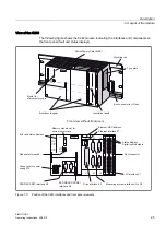
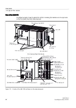
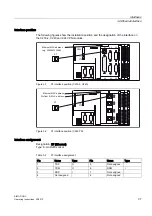
The following LED displays are on the front panel of the SIMOTION C. This table describes
the LEDs and their function.
Table 2- 2
Status and error displays
LED
Meaning
SF (red)
This LED indicates a fault on the SIMOTION C.
5 VDC (green)
This LED indicates that the power supply for the electronics is ready.
RUN (green) -
SIMOTION C in RUN mode
This LED indicates that the user program is running.
STOPU (yellow) -
SIMOTION C in STOP user
program mode
This LED indicates that the technology packages (for example,
synchronous operation and cam) are active. The user program is not
active.
STOP (yellow) -
SIMOTION C in STOP mode
This LED indicates that no user program is running. The technology
packages are not active.
BUS1F (red) -
Group fault
This LED indicates a fault on the SIMOTION C PROFIBUS DP1
interface (X8).
BUS2F (red) -
Group fault
This LED indicates a fault on the SIMOTION C PROFIBUS DP2/MPI
interface (X9).
Q0 to Q7 , I0 to I11 ,
B1 to B4, M1, M2 (green) -
Digital inputs/digital outputs
These LEDs show the status of the digital inputs/outputs.
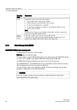
The following LED displays are arranged the front cover of the SIMOTION C240 PN. This
table describes the LEDs and their function.
Table 2- 3
Status and fault displays behind the front cover (C240 PN)
LED
Meaning
Ethernet link (X7) (green)
This LED indicates a physical connection of the Ethernet
interface.
Ethernet activity (X7) (yellow)
This LED indicates a data transfer via the Ethernet interface.
PROFINET link (X11 Px) (green)
This LED indicates a physical connection of the PROFINET
interface at port x.
PROFINET activity (X11 Px) (yellow) This LED indicates a data transfer via the PROFINET
interface at port x.
PROFINET fault (X11) (red)
This LED indicates a fault at the PROFINET interface.
PROFINET sync (X11) (green)
This LED indicates synchronization status of the PROFINET
interface.
See also


