Connecting
5.1 Wiring
SIMOTION C
Operating Instructions, 02/2012
115
Procedure for connecting encoders
Proceed as follows to connect the encoders:
1.
Connect the cable to the encoders.
2.
Open the front cover of the C230-2, C240 and insert the Sub-D connectors (15-pin) into
sockets X3 to X6.
3.
Lock the connector using the finger screws. Close the front cover.
Connecting cables available for encoders
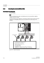
The following connecting cables are available (see figure "Overview of connections"):
● Pre-assembled cable for external encoder or EXEs (for the connection of linear position
encoders)
● Pre-assembled cable for built-in encoder with 17-pin round connector
● Pre-assembled cable for absolute encoders (SSI)
● Pre-assembled cable for SIMODRIVE 611 analog closed-loop control module 1FK6
motors with resolver
● Pre-assembled cable for SIMODRIVE 611 universal with incremental shaft encoder
interface
The incremental shaft encoder interface is used to emulate an incremental encoder. For
this, the actual position value is measured by the encoder connected to the drive unit and
transmitted to the C230-2, C240 as an incremental counting pulse.
The encoder supply provided on the C230-2 and C240 is not used. Make sure there is a
good ground connection between the controller and drive unit.
The connecting cables are available in a choice of lengths.
See
Catalog PM 21, NC 60, or ST 70


