Getting Started
Fail-Safe Systems
2-6
A5E00085588-03
2.2.2
Configuring the S7 F System
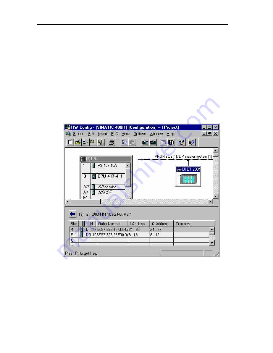
The following steps show you how to create a new project and configure the
hardware setup described above.
Procedure
1.
Open SIMATIC Manager, and create a new project called "FProject" using the
File > New menu command.
2.
Insert a new S7-400 station: Insert > Station > SIMATIC 400 Station.
3.
Open the hardware configuration (HWCONFIG) of the SIMATIC 400(1) station
created (you can change the name) by double-clicking the hardware object (or
right-click the Open Object pop-up menu command).
4.
Insert the individual hardware components of the SIMATIC 400 from the
"Hardware Catalog" window (you can open the catalog with View > Catalog)
by dragging and dropping them to the station window.
5.
First place the UR2 mounting rack from the RACK 400 catalog.
6.
Insert the standard power supply (PS 407 10 A) in slot 1 of the mounting rack.
7.
Place the CPU 417-4H V3.1 in slot 3: Create a subnet (which will subsequently
be connected to the ET 200M) in the "Properties - PROFIBUS Interface DP
Master" dialog box by clicking New.
Содержание SIMATIC S7 F
Страница 8: ...Important Information Fail Safe Systems viii A5E00085588 03 ...
Страница 16: ...Contents Fail Safe Systems xvi A5E00085588 03 ...
Страница 38: ...Product Overview Fail Safe Systems 1 22 A5E00085588 03 ...
Страница 56: ...Getting Started Fail Safe Systems 2 18 A5E00085588 03 ...
Страница 70: ...Safety Mechanisms Fail Safe Systems 3 14 A5E00085588 03 ...
Страница 115: ...Programming Fail Safe Systems A5E00085588 03 5 33 Examples Receive Block Send Block ...
Страница 154: ...Programming Fail Safe Systems 5 72 A5E00085588 03 ...
Страница 166: ...Operation and Maintenance Fail Safe Systems 6 6 A5E00085588 03 ...
Страница 332: ...Fail Safe Blocks Fail Safe Systems 8 144 A5E00085588 03 ...
Страница 344: ...References Fail Safe Systems B 2 A5E00085558 03 ...
Страница 350: ...Glossary Fail Safe Systems Glossary 6 A5E00085588 03 ...


