Siemens SIMATIC PRO Extension Unit 12

Configuring Extension Unit PROFINET and PROFIsafe 


4.4 Configuring Advanced operator controls 


Extension Units KPxx 

68


Operating Instructions, 05/2019, A5E43600360-AC 

4.


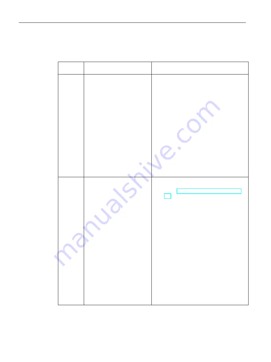
Assign the parameters of the operator control in the property window. 

Properties of the Advanced operator controls 


Operator  

control 

Input (contact) 

Output (LED) 

RGB  

illuminated 

pushbutton 

1 byte (0.0 … 0.7), of which bit 0.0 


"0": Pushbutton not pressed 


"1": Pushbutton pressed 

2 bytes (0.0 … 0.7, 1.0 … 1.7) 
Byte 0: Color 


3 bits (0.2|0.1|0.0): LEDs (red+green+blue) 


"100": Red 


"010": Green 


"001": Blue 


"110": Yellow 


"111": White 


"000": Off 


"101": Off 


"011": Off 

Byte 1: Brightness in 255 levels 


0: Dark (off) 


1: Minimum 


255: Maximum 

KP12 

2 bytes (0.0 … 0.7, 1.0 … 1.7) 


"0": Pushbutton not pressed 


"1": Pushbutton pressed 


Bit 0.0: Pushbutton 1 


Bit 0.7: Pushbutton 8 


Bit 1.0: Pushbutton 9 


Bit 1.3: Pushbutton 12 

13 bytes (0.0 … 0.7,…, 11.0 … 11.7) for the 

pushbuttons: Counting from top left to bottom right 

(see section "Advanced installation components 

(Page 21)") 
Byte n = 0 to 11:  

Color of the pushbuttons 1 to 12 


3 bits (n.2|n.1|n.0): LEDs (red+green+blue) 


"100": Red 


"010": Green 


"001": Blue 


"110": Yellow 


"111": White 


"000": Off 


"101": Off 


"011": Off 

Byte 12: Uniform brightness of all buttons in 255 

steps 


0: Dark (off) 


1: Minimum 


255: Maximum 


Содержание SIMATIC PRO Extension Unit 12" F PN Advanced

Страница 1: ...Operating Instructions 05 2019 A5E43600360 AC Preface Overview 1 Safety instructions 2 Mounting and connecting the Extension Unit 3 Configuring Extension Unit PROFINET and PROFIsafe 4 Device maintenance and repair 5 Technical specifications 6 Technical support A Markings and symbols B ...

Страница 2: ...by personnel qualified for the specific task in accordance with the relevant documentation in particular its warning notices and safety instructions Qualified personnel are those who based on their training and experience are capable of identifying risks and avoiding potential hazards when working with these products systems Proper use of Siemens products Note the following WARNING Siemens product...

Страница 3: ...KP12 maximum configuration Extension Unit 19 KP36 PN 6AV2185 8EE08 0AA0 3 KP12 maximum configuration Extension Unit 22 KP48 PN 6AV2185 8FE08 0AA0 4 KP12 maximum configuration Extension Units Standard customized Customized Extension Units Standard with pre installed standard operator controls xxxx Name MLFB Based on Extension Unit 12 Hardwired 6AV2185 8CBxx xxxx 6AV7674 1LA31 0AA0 Extension Unit 15...

Страница 4: ...ectly to the system all other signals are transmitted via PROFINET Extension Unit 15 KP12 PN 6AV2185 8DEx1 xxxx Extension Unit 19 KP12 PN 6AV2185 8EEx1 xxxx Extension Unit 22 KP12 PN 6AV2185 8FEx1 xxxx Extension Unit 12 KP12F PN 6AV2185 8CFx1 xxxx 1 KP12F minimum configuration fail safe PN All IO signals are transmitted via PROFINET PROFIsafe Extension Unit 15 KP12F PN 6AV2185 8DFx1 xxxx Extension...

Страница 5: ...it 15 KP36 PN Extension Unit 19 KP36 PN Extension Unit 22 KP48 PN Extension Unit PROFIsafe Standard Extension Unit 12 PROFIsafe Extension Unit 15 PROFIsafe Extension Unit 19 PROFIsafe Extension Unit 22 PROFIsafe Extension Unit PROFIsafe Advanced Extension Unit 12 KP12F PN Extension Unit 15 KP12F PN Extension Unit 19 KP12F PN Extension Unit 22 KP12F PN Extension Unit PROFINET Extension Unit PROFINE...

Страница 6: ...ndard and Advanced such as interface components Interface components USB port RFID reader Advanced installation components Advanced operator controls and all other components that can only be installed in an Extension Unit Advanced Installation elements Standard installation components Advanced installation components Communication module Hardwired Communication module of an Extension Unit Hardwir...

Страница 7: ...he emergency stop button 28 3 Mounting and connecting the Extension Unit 29 3 1 Assembly overview 29 3 2 Preparing the installation 29 3 2 1 Checking the delivery package 29 3 2 2 Permitted mounting positions 30 3 2 3 Specifying the operator controls and slots 31 3 2 4 Cable lengths for the Extension Unit Advanced 36 3 2 5 Preassemble the short stroke adapter 38 3 3 Important notes for installatio...

Страница 8: ...iguring standard operator controls 70 4 7 Extension Unit PROFIsafe Configuring emergency stop buttons 73 4 8 Extension Unit PROFIsafe Safety configuration 74 5 Device maintenance and repair 79 5 1 General information on maintenance and servicing 79 5 2 Cleaning the device 79 5 3 Spare parts and repairs 80 5 4 Recycling and disposal 80 6 Technical specifications 81 6 1 Certificates and approvals 81...

Страница 9: ...ndividually wired The Extension Unit Standard is usually delivered without operator controls The Extension Unit Standard is also available as a customized version Extension Unit Advanced for Advanced operator controls such as RGB illuminated pushbuttons that are connected through an internal bus Standard operator controls such as illuminated pushbuttons emergency stop buttons and interface compone...

Страница 10: ...ection of operator controls Rugged System integration also available with PROFIsafe Full flexibility Extension Units 12 15 19 22 can be equipped with all operator controls Freely configurable color red green blue white yellow Easy adaptation to customer requirements using the internal bus Extension Unit Advanced Individually adjustable LED backlight with adjustable color and brightness at runtime ...

Страница 11: ...at differ in width and number of slots Extension Unit 12 with 6 slots Extension Unit 15 with 8 slots Extension Unit 19 with 10 slots Extension Unit 22 with 12 slots You can also combine each Extension Unit with any display size If additional operator controls are required a second Extension Unit can be installed under the PRO device Up to 8 standard operator controls and 2 emergency stop buttons c...

Страница 12: ...e below shows a device version in each line and the maximum possible configuration with installation components in the columns for each KPxx configuration level Configuration level Device version Empty configuration a PROFINET or b PROFIsafe Minimum configuration a PROFINET or b PROFIsafe Full configuration PROFINET only Installation components KP12 Operator controls if 0 1 RFID 2 RFID 3 KP12 Oper...

Страница 13: ...n ongoing production process 12 short stroke keys with integrated LEDs The LEDs allow the display of different colors Red green blue yellow and white can only be set in runtime The common brightness of all LEDs can be adjusted individually for each KP12 Communication via PROFINET Configuration via TIA Portal SIMATIC design Through this the HMI devices can be arranged closely next to each other Log...

Страница 14: ...upply connector for 24 V DC 4 M4x20 screws for mounting the Extension Unit to the SIMATIC PRO device Quick Install Guide Extension Unit PROFINET 1 Extension Unit 1 plug in connector 8 pin for X10 interface 1 power supply connector for 24 V DC 4 M4x20 screws for mounting the Extension Unit to the SIMATIC PRO device Quick Install Guide Extension Unit PROFIsafe 1 Extension Unit 1 power supply connect...

Страница 15: ...Extension Units using the Extension Unit 22 as an example Front view Mechanical interface to the PRO device with seal Enclosure Front Side view Enclosure Terminal compartment cover Connection compartment Mechanical interface to a stand to an Extension Unit or for the bottom cover in case of sup port arm mounting Rear view Enclosure Rear panel cover Recess for the nameplate ...

Страница 16: ...nit PROFINET and Extension Unit PROFIsafe the slots are numbered similar to the display in the TIA Portal in ascending order from left to right The numbering in this and the following figure corresponds to STEP 7 TIA Portal V15 for V14 the numbering of the slots from 1 to 12 applies Rear The figure below show the enclosure without a rear panel cover using the Extension Unit 22 as an example Markin...

Страница 17: ...o right their slot numbers are also sequentially numbered from 14 left to 22 right Note Connection sequence slot number 14 The order in which the connection cables are inserted connection sequence see rear panel determines the slot number The first Advanced installation component connected to the internal bus always has slot number 14 because the first 13 numbers are reserved for the Standard inst...

Страница 18: ... connecting cables see section Cable lengths for the Extension Unit Advanced Page 36 Interfaces of the communication modules You can find a description of the interfaces of the respective communication module in the connection compartment of the Extension Unit in the section Technical specifications Page 81 1 4 Standard installation components Only installation elements with Siemens approval may b...

Страница 19: ...ontrol 1 NO contact Back lit button with 5 lens assemblies red yellow green blue white Blue 6AV7674 1MB00 0AA0 Illuminated pushbutton 2 contacts Standard operator control 1 NC contact 1 NO contact Back lit button with 5 lens assemblies red yellow green blue white Yellow 6AV7674 1MG00 0AA0 Indicator light Standard operator control Indicator light with 5 lens assemblies red yellow green blue white O...

Страница 20: ...ls installation on outside of operator control 6AV7674 1LB20 0AA0 Interface components Name Description MLFB USB port USB port for installation on the front of the Extension Unit USB 2 0 Type A cable and plug 6AV7674 1MF00 0AA0 Reader The figure below shows the reader SIMATIC RF1060R with the optional Card holder for RF1060R Reader SIMATIC RF1060R including USB connection cable article number 6GT2...

Страница 21: ... module Required fasteners Connecting cable of the internal bus The table below shows a selection of operator controls that have been approved for the Extension Unit Advanced Figure Name Description MLFB for configuration RGB illuminated pushbutton Advanced operator control 1 NO contact Illuminated pushbutton with 4 LEDs colors red green blue yellow white RGB colors individually configurable 6AV21...

Страница 22: ...umbering of the associated LEDs The corresponding bit in the connected controller is set as long as the pushbutton is pressed Flat LEDs are built into each pushbutton and controlled by appropriate bits The LEDs can show the colors red green blue yellow and white The brightness of the LEDs is adjustable The pushbuttons are evaluated using the process image see section Configuring Advanced operator ...

Страница 23: ...is mounted to a SIMATIC PRO device the safety instructions and application notes in the SIMATIC PRO operating instructions also apply 2 2 General safety instructions The device is designed for operation in industrial areas for operator control and monitoring of plant processes WARNING Personal injury or material damage due to non compliance with safety regulations Failure to exactly comply with th...

Страница 24: ...program with values from the load memory can also be initiated by a handling error or an internal error If the process does not permit this a re start protection must be programmed in the safety program The output of process values must be disabled until manually enabled this must not occur until the process values can be output without posing a hazard and errors have been eliminated Note Observe ...

Страница 25: ...m 2 Secure the system to prevent it switching back on 3 Check the system to ensure it is de energized 4 Ground and short the system 5 Cover or shield adjacent live parts Note These safety steps must always be taken in the above order before any work on electrical systems Once work on an electrical system is finished cancel the safety steps starting with the last and finishing with the first Label ...

Страница 26: ...lsecurity Siemens products and solutions undergo continuous development to make them more secure Siemens strongly recommends that product updates are applied as soon as they are available and that the latest product versions are used Use of product versions that are no longer supported and failure to apply latest updates may increase customer s exposure to cyber threats To stay informed about prod...

Страница 27: ...nce EN 61000 6 4 A1 Requirements for interference immunity EN 61000 6 2 Use in mixed use zone Under certain circumstances you can use the device in a mixed use zone A mixed use zone is used for housing and commercial operations that do not have a significant impact on residents When you use the device in a mixed use zone you must ensure that the limits of the generic standard EN 61000 6 3 regardin...

Страница 28: ...ns are needed locally in a plant segment or globally throughout the plant and which operating mode is to be used for the devices in a safety related plant area Take the plant configuration as a whole into consideration in the risk analysis and not just the individual areas Additional information on risk analysis and risk mitigation is available at Safety Technology in SIMATIC S7 system manual http...

Страница 29: ...livery package Procedure 1 When accepting a delivery please check the packaging for visible transport damage 2 If any transport damage is present at the time of delivery lodge a complaint at the shipping company in charge Have the shipper confirm the transport damage immediately 3 Unpack the device at its installation location 4 Keep the original packaging in case you have to transport the unit ag...

Страница 30: ...d up on or inside the device condensation Moisture causes a short circuit in electrical circuits and damages the device In order to prevent damage to the device proceed as follows Store the device in a dry place Bring the device to room temperature before starting it up Do not expose the device to direct heat radiation from a heating device If condensation develops wait until the device is complet...

Страница 31: ... to 13 1 is reserved for the communication module The number of slots is limited on the right to the display size maximum 12 slots 22 device version 3 With Extension Units PROFINET and PROFIsafe Advanced the slot numbers for Advanced operator controls are sequentially numbered in the order of their wiring see rear panel from 14 to 45 The slot numbers also refer to the implementation in the TIA Por...

Страница 32: ... in diameter takes up the slot of an operator control An emergency stop button with a yellow ring 60 mm in diameter covers up the adjacent slots and therefore takes up Two slots when the emergency stop button is installed in an outer slot Three slots when the emergency stop button is installed between two slots An RFID reader can be installed in the free slots on the left or right The reader cover...

Страница 33: ...ol either left L or right R Extension Unit 22 Hardwired 12 slots maximum of 10 operator controls maximum of 8 standard operator controls Connected slots may only be occupied by one standard operator control either left L or right R Assignment example for an Extension Unit Hardwired The figure below shows an example of how to install 8 standard operator controls in an Extension Unit Hardwired 22 an...

Страница 34: ...sion Unit Advanced The following applies to Extension Units Advanced Slots can be moved to a second Extension Unit as required A maximum of 32 installation components can be configured Note Slot 14 in delivery state In the delivery state of the minimum configuration 1 KP12 ex works the connecting cable from the communication module is connected to the KP12 The KP12 is therefore the first operator ...

Страница 35: ...4 2 Connect the output of the installation component KP12 to any connection input of the left RGB illuminated pushbutton It is assigned slot number 15 Because of the gap in between you need a long connecting cable see section Cable lengths for the Extension Unit Advanced Page 36 3 Connect the second RGB illuminated pushbutton via the remaining output Slot number 16 You need a longer connecting cab...

Страница 36: ...ion The following figure and table provide an overview of which connecting cables you will need if there are slots between the cables that are to be skipped NOTICE Minimum configuration KP12 covers slots Even if an operator control directly adjoins the KP12 there is still one slot in between This additional slot in the KP12 must be counted 1 when you wire the KP12 Number of slots in between requir...

Страница 37: ...IA Portal starting with14 without a gap from left to right must match the slot number Example KP12 14 1 Traffic light RGB_green 15 RGB_yellow 16 RGB_red 17 The corresponding operator controls must be wired in exactly this order even if they are equipped the other way around 1 In the delivery state of the minimum configuration 1 KP12 ex works the KP12 is located at slot 14 1 The dashed circles show...

Страница 38: ...le the short stroke adapter With some Advanced operator controls a short stroke adapter shortens the path of the lens assemblies Operation appears more precise and the reaction more immediate Preassemble the short stroke adapter on the operator control Procedure 1 Install the spring to the left of the short stroke adapter as shown 2 Insert the short stroke adapter into the operator control from be...

Страница 39: ... Extension Unit or the PRO device caused by unsuitable screws Screws made from unsuitable material and screws of an incorrect dimension may damage the Extension Unit or the PRO device Use only the screws supplied in the accessory kit for the Extension Unit Do not exceed torques When you tighten the screws with an excessive torque you can damage the threading in the enclosure Tighten the screws wit...

Страница 40: ...ired as an example Procedure 1 Loosen the 2 screws of the terminal compartment cover with a T20 screwdriver and remove the terminal compartment cover 2 Loosen the 4 screws of the communication module with a T10 screwdriver and carefully put down the communication module 3 Loosen the four screws of the connection compartment with a T20 screwdriver and carefully put down the connection compartment T...

Страница 41: ...nit on a soft surface to avoid scratching the front The following description is based on the standard position of the Extension Unit which means as views from the inside with the cable harness below the marking above The following description shows the installation of an operator control using the example of an illuminated pushbutton The emergency stop button is installed in the same way 1 Remove...

Страница 42: ...ition from the front of the Extension Unit the nipple for anti twist protection must point up 4 Fasten the operator control from the inside with the supplied nut torque 1 2 Nm 5 Insert the connection module of the operator control into the Extension Unit so that the plug in connector is at the top Fasten the connection module onto the enclosure of the Extension Unit at the marked locations torque ...

Страница 43: ...e brown green from left to right as viewed from inside of Extension Unit The emergency stop button connector left as viewed from front view of the Extension Unit from the outside is marked with blue adhesive tape the emergency stop button connector right as viewed from the front view of the Extension Unit from the outside is marked with red adhesive tape Note Extension Unit PROFIsafe with emergenc...

Страница 44: ...ess emergency stop to the 6 pin connector of an operator control Do not try to connect the 6 pin connector of the wiring harness to the 5 pin connector of the emergency stop Do not try to connect the 6 pin internal bus connector Advanced operator controls to the 6 pin connector of a Standard operator control Do not try to connect the 6 pin connector of the wiring harness Standard operator controls...

Страница 45: ...t This installation component is given the connection designation n When this installation component is connected directly to the communication module it receives the terminal designation 14 Insert the plug of another connecting cable of suitable length into the output Repeat the steps with the other connector of the connecting cable Insert it into the connector of another connection module which ...

Страница 46: ...lace the Extension Unit on a soft surface to avoid scratching the front The following description is based on the standard position of the Extension Unit which means as viewed from the inside with the cable harness below the marking above 1 Cut out the foil on the inside of the Extension Unit along all cutouts required for the reader with a sharp knife Notice Only cut within the cutouts 2 Insert a...

Страница 47: ...ader Make sure that you do not pinch the USB cable 6 Fasten the cover of the reader with the 4 supplied tapping screws M3x10 torque 1 2 Nm 7 Secure the reader as shown in the figure above with two of the supplied set screws M4x20 in the Extension Unit Use a slotted size 2 screwdriver torque 0 5 Nm It may happen that the two threaded shackles on the cover of the reader bend slightly when they are s...

Страница 48: ...s are installed fasten the rear panel cover to the enclosure of the Extension Unit as shown in the figure below NOTICE Do not pinch cables plug Xnn visible in the cutout When fastening the rear panel cover make sure that you do not pinch the cables and that the Xnn connectors remain visible in the cutout of the rear panel cover so that they are easily accessible Tighten the 4 marked screws with a ...

Страница 49: ...r was removed from the PRO device Preparations Installation of two Extension Units Fasten the connection compartment of the bottom Extension Unit with four T20 screws to the mechanical interface of the top Extension Unit with a torque of 2 5 Nm Proceed as described to install an individual Extension Unit Stand mounting Fasten the connection compartment to the mechanical interface of the pedestal w...

Страница 50: ... Unit to the PRO device The figure below shows an Extension Unit Hardwired as an example 1 Fasten the connection compartment onto the PRO device as shown below with a torque of 2 5 Nm using the 4 screws and the angled T20 screwdriver included in the product package 2 Fasten the communication module to the connection compartment with 4 T10 screws and a torque of 0 8 Nm ...

Страница 51: ...ct the connector to the following interfaces of the communication module 30 pin connector of the cable harness blue adhesive tape with X17 Standard and Advanced 30 pin connector of the cable harness red adhesive tape with X15 Standard and Advanced 6 pin connector of the internal bus with X16 Advanced only The cable harnesses of the connectors are marked with colored adhesive tape as follows 2 Fast...

Страница 52: ... address that is set on the PROFIsafe device This section describes how to set the PROFIsafe address in an Extension Unit PROFIsafe Requirement The Extension Unit PROFIsafe is mounted The connection compartment of the Extension Unit PROFIsafe is open A PROFIsafe address has been specified for the Extension Unit PROFIsafe Procedure 1 De energize the Extension Unit PROFIsafe 2 Set the PROFIsafe addr...

Страница 53: ...witch settings correspond with the binary address 383 See also Extension Unit PROFIsafe Safety configuration Page 74 3 13 Connecting an Extension Unit 3 13 1 Connection information Connecting cables Note Use copper cables a the connectors with terminal connections Use the copper Cu cables for all supply lines that are connected to the device with terminals for example 24 V DC power supply cables t...

Страница 54: ...of the ports is described in the technical specifications 3 13 2 Connecting the functional grounding Requirement The Extension Unit is mounted 1 cable for functional grounding cross section 2 5 to 4 mm2 with cable lug for M4 is threaded through the pedestal or support arm to the connection compartment 1 T20 screwdriver Procedure The figure below shows the communication module of an Extension Unit ...

Страница 55: ...ons Page 84 Incorrect voltage may cause malfunctions Applies to non isolated system configurations Connect the GND 24 V connection from the 24 V power supply output to equipotential bonding for uniform reference potential You should always select a central point of termination NOTICE External protective circuit An external protective circuit is required for operation with 24 V DC see section 7 Lig...

Страница 56: ...ata cables Requirement The Extension Unit is mounted Depending on the type of the Extension Unit the following connection cables are threaded though the stand or support arm to the connection compartment Extension Unit Hardwired Extension Unit PROFINET Extension Unit PROFIsafe Cables for the digital inputs outputs of the operator controls cross section 0 14 1 5 mm2 Connection cables for the button...

Страница 57: ...op button X10 connector PROFINET cable Angled PROFINET connector Extension Unit PROFIsafe PROFINET cable Angled PROFINET connector Note Angled PROFINET connector required for Extension Unit PROFINET and PROFIsafe The connection compartment of the Extension Unit can only be closed properly when you use an angled PROFINET connector You can find details on wiring the connectors X10 X11 and X12 in the...

Страница 58: ...xtension Unit PROFINET and the Extension Unit PROFIsafe Clamp the shield of the PROFINET cable from the Extension Unit flush at the rail for the functional grounding using suitable cable clamps as seen in the figure below The rail for functional grounding should be installed close to the Extension Unit or the device Route the functional grounding cable and the data cables in parallel and with mini...

Страница 59: ... example The cables are secured and the Extension Unit PROFINET and PROFIsafe are closed in the same way 1 Use cable ties to secure the connected cables to the selected fasteners of the communication module for strain relief 2 Fasten the rear panel cover back onto the connection compartment with a T20 screwdriver and a torque of 1 5 Nm 3 When you have mounted the Extension Unit to a PRO device for...

Страница 60: ...n This is needed to insert the labeling strips The maximum permitted thickness of the labeling strip is 0 15 mm Note Wait for the printed labeling strips to dry before you insert them 3 Cut out the labeling strip Ensure that the corners are cut according to the corresponding diagram as this makes it easier to slide them into the slot 4 Remove any previously existing labeling strips 5 Slide the new...

Страница 61: ... 3 15 2 Mounting insert labels and the lens assemblies Features Perforated DIN A4 labeling sheet for custom printing Template is available for download Only suitable for indicator lights and illuminated pushbuttons Procedure See also Label template for Extension Units https support industry siemens com cs ww en view 109746380 ...

Страница 62: ...9 A5E43600360 AC 3 15 3 Mounting label holders Features Using transparent PMMA foil Template available as download for custom labeling Suitable for all operator controls except emergency stop button Procedure See also Label template for Extension Units https support industry siemens com cs ww en view 109746380 ...

Страница 63: ...nstallation of the Hardware Support Package for the Extension Unit PROFIsafe The figures in the following sections correspond to STEP 7 TIA Portal V15 in combination with the respective HSP and may deviate from the display on your configuration PC in some detail 4 2 Required Advanced software You need STEP 7 TIA Portal V14 or higher and a Hardware Support Package to configure Extension Unit PROFIN...

Страница 64: ...IP65 fully enclosed devices Extension Unit Standard Standard operator controls only Select the appropriate Extension Unit in the Extension Units folder Extension Unit Advanced for Advanced operator controls In the Advanced communication module folder select the appropriate communication module that always supports Standard and Advanced operator controls Place the appropriate Extension Unit or appr...

Страница 65: ... standard operator controls that you can find in the catalog tree under Operator Controls for example the illuminated pushbuttons see above The largest Extension Unit 22 has a maximum of 12 standard mounting positions CAUTION Danger due to incorrect configuration of the mounting positions The device view does not show the actual mounting positions For example a maximum of 8 slots are actually avai...

Страница 66: ...s from left to right in the exact order in which they are connected to the internal bus Configure the Advanced operator controls sequentially without gaps in between Do not configure more Advanced operator controls than the number of Advanced operator controls actually installed The power consumption for the Advanced operator controls is limited see section Power consumption of the Advanced operat...

Страница 67: ... the corresponding section in the chapter Specifying the operator controls and slots Page 31 The configuration is the same as for the Standard operator controls Requirement The necessary software is installed A project with a communication module is open The Device view is open Procedure 1 In the device view select the desired communication module 2 Select the required operator control in the cata...

Страница 68: ...green blue 100 Red 010 Green 001 Blue 110 Yellow 111 White 000 Off 101 Off 011 Off Byte 1 Brightness in 255 levels 0 Dark off 1 Minimum 255 Maximum KP12 2 bytes 0 0 0 7 1 0 1 7 0 Pushbutton not pressed 1 Pushbutton pressed Bit 0 0 Pushbutton 1 Bit 0 7 Pushbutton 8 Bit 1 0 Pushbutton 9 Bit 1 3 Pushbutton 12 13 bytes 0 0 0 7 11 0 11 7 for the pushbuttons Counting from top left to bottom right see se...

Страница 69: ...umption of the Advanced operator controls Under General Energy consumption in the properties of the communication module the power consumption is shown for each Advanced operator control Module and the total sum A communication module supplies the connected Advanced operator controls with maximal 24 W An RGB illuminated pushbutton consumes approx 0 5 W A KP12 module needs approx 2 6 W When the pow...

Страница 70: ...e other standard operator controls are configured in the same way Requirement The necessary software is installed You have opened a project with Extension Unit The Device view is open Procedure 1 Select the required Extension Unit in the Device view 2 Select the required operator control in the catalog tree 3 Drag the required operator control to the preferred mounting position The mounting positi...

Страница 71: ...d pushbutton 1 1 NC contact 1 NO contact 2 bits 7 1 7 0 10 Pushbutton is not pressed 01 Pushbutton is pressed 1 bit 0 LED off 1 LED on Selector switch 2 bits 7 1 7 0 2 00 Position Center 01 Position Right 10 Position Left 1 bit 0 LED off 1 LED on Keyswitch 2 bits 7 1 7 0 2 00 Position Center 10 Position Right 01 Position Left 1 The color of the lens assembly for representation in the device view T...

Страница 72: ...n the cyclical output data for the controller IOPS Input Output Object Provider Status Emergency stop button Emergency stop buttons are not configured with the Extension Unit PROFINET They are hardwired instead using the X10 interface Note Configure emergency stop button only for Extension Unit PROFIsafe When you place an emergency stop button in a slot of the Extension Unit PROFINET an error mess...

Страница 73: ...signed with the parameter assignment of the F module of the Extension Unit PROFIsafe The F module has an input address with 5 bytes and an output address of 4 bytes Requirement The necessary software is installed You have opened a project with Extension Unit PROFIsafe The Device view is open Procedure 1 Select the required Extension Unit PROFIsafe in the Device view 2 Select an emergency stop butt...

Страница 74: ...s for PROFIsafe communication with a PROFIsafe device in a system Note The PROFIsafe address of a PROFIsafe device must be unique throughout the network and station You can assign a maximum of 1022 PROFIsafe addresses in a single system The configured PROFIsafe address must match the PROFIsafe address that is set on the PROFIsafe device This section describes how to configure the PROFIsafe address...

Страница 75: ...5 An F runtime group exists To check select the Program blocks entry under the PLC in the device view The input address of the Extension Unit PROFIsafe is evaluated at least once in the F runtime group The number of the F I O DB is located below the PROFIsafe parameters of the Extension Unit PROFIsafe in the F I O DB number box see figure below The Device view is open ...

Страница 76: ...yellow frame 3 In the PROFIsafe properties select the entry Module parameters 4 Select the operating mode according to the plant specification Default setting is 5454h for the 1oo2 mode for both emergency stop buttons The input address contains the information on the status of the emergency stop buttons pressed 0 not pressed 1 see section Operating modes of the Extension Unit PROFIsafe Page 88 5 I...

Страница 77: ... of the F runtime group The status of the F runtime group can be read out for example by means of the F I O DB The following outputs are of major importance for commissioning QBAD An error has occurred in the device the device outputs substitute values ACK_REQ The device can be activated again for example with ACK_REI or globally with the instruction ACK_GL from the library Basic instructions Safe...

Страница 78: ...teps to display the diagnostic information of an Extension Unit PROFIsafe that is connected to a PLC 1 Press the Go online button 2 Select slot 0 of the Extension Unit PROFIsafe in the device view and click on the green check mark in the top right hand corner of the safety module The Diagnostics window opens In the Diagnostics window you have access to the advanced functions Firmware update and Re...

Страница 79: ...ng on the degree of contamination At regular intervals according to an internal cleaning plan CAUTION Unwanted reactions when cleaning the device You risk unintentional actuation of operator controls if you clean the device while it is switched on You may possibly trigger unwanted actions of the device or controller that are liable to cause personal injury or damage to the machinery Before you sta...

Страница 80: ...turn Center in Erlangen The address is Siemens AG Digital Factory Retouren Center c o Geis Service GmbH Tor 1 4 Kraftwerkstraße 25a 91056 Erlangen Germany You can find detailed information on the Internet at Spare parts and repairs http support automation siemens com WW view en 16611927 Spare parts You can find spare parts and accessories for the HMI device in section Standard installation compone...

Страница 81: ...ovals For the device itself only the approvals shown on the rear of the device apply CE approval The device meets the general and safety related requirements of the following EU directives and conforms to the harmonized European standards for programmable logic controllers published in the official gazettes of the European Union 2014 30 EU Electromagnetic Compatibility Directive EMC Directive 2014...

Страница 82: ...writers Laboratories Inc to UL 508 Industrial Control Equipment CSA C22 2 No 142 Process Control Equipment RCM AUSTRALIA NEW ZEALAND This product meets the requirements of the standards AS NZS 61000 6 4 IEC 61000 6 4 Identification for Eurasion Customs Union EAC Eurasian Conformity Customs union of Russia Belarus and Kazakhstan Declaration of conformity according to Technical Regulations of the Cu...

Страница 83: ...rs Part 2 Equipment requirements and testing IEC 61326 3 1 2017 and 2 2017 Electrical equipment for measurement control and laboratory use EMC requirements Part 3 2 Immunity requirements for safety related systems and for equipment intended to perform safety related functions functional safety TÜV The German Technical Inspectorate TÜV confirms that the Extension Unit PROFIsafe satisfies the requir...

Страница 84: ... Unit 12 Extension Unit 15 Extension Unit 19 Extension Unit 22 W 313 mm W 396 mm W 462 mm W 527 mm All dimensions in mm 6 4 Technical specifications 6 4 1 General technical specifications Weight and dimensions The following information applies to all versions of the Extension Units Weight 12 approx 2200 g 15 approx 2500 g 19 approx 2700 g 22 approx 2800 g Dimensions W H D 12 313 99 100 65 mm 15 39...

Страница 85: ...fall in device packaging Maximum 0 3 m Vibration Sinusoidal vibrations tested to IEC 60068 2 6 Operation 5 to 8 4 Hz Amplitude 3 5 mm 8 4 to 200 Hz 9 8 m s2 Storage transportation 5 to 8 4 Hz Amplitude 3 5 mm 8 4 to 500 Hz 9 8 m s2 Resistance to shock Tested in accordance with IEC 60068 2 27 Operation Half sine peak value 15 g duration 11 ms Storage transportation Half sine 250 m s2 6 ms 1000 shoc...

Страница 86: ...between different circuits No Reverse polarity protection Yes 1 The power loss generally corresponds to the specified value for power consumption 2 Power consumption with load additional 0 1 W per operator control with LED 3 Power consumption with load additional 0 5 W per RGB illuminated pushbutton and 2 6 W per KP12 Maximum permissible terminal power rating total power rating 24 W Interfaces Ext...

Страница 87: ...e 0 5 A With lamp load max 5 W DC Short circuit protection Yes Output delay with resistive load 0 after 1 max 3 ms 1 after 0 max 3 ms Extension Unit PROFINET Extension Unit PROFIsafe Input current Switching capacity of the outputs According to PROFINET PROFIsafe speci fication Electrical isolation between different circuits No Number of standard operator controls maximum 12 per operator control Nu...

Страница 88: ...gency stop button to 24 V DC safety monitoring e g Siemens 3SK1 series or fail safe digital inputs required See also Advanced installation components Page 21 Standard installation components Page 18 6 4 2 Operating modes of the Extension Unit PROFIsafe The following table shows the assignment between emergency stop buttons operating modes and the bits of the input address that is set when an emerg...

Страница 89: ...dangerous failure per hour PFH 6 10 10 1 h 3 10 10 1 h Probability of a dangerous failure on demand PFD 8 10 5 8 10 5 Diagnostic test interval 15 ms 15 ms Proof Test Interval 1 x per year 1 x per month Lifetime 20y 20y In accordance with IEC 13849 1 Meantime to Failure MTTFd high high Meantime to Restoration MTTR 100 h 100 h Diagnostic Coverage DCavg high high Performance level d e Category 3 4 Al...

Страница 90: ...Hardwired External interfaces on the communication module of the Extension Unit PROFINET External interfaces on the communication module of the Extension Unit PROFIsafe The following sections describe The pin assignment of the interface X80 POWER The pin assignment and the switching states of the digital inputs outputs at the following interfaces X12 CONTACT and X11 LED of the Extension Unit Hardw...

Страница 91: ...igital inputs outputs Contacts of the standard operator controls X12 Pin left connected to slot position Pin right connected to slot position 1 L3 R6 1 R6 L3 2 L4 R5 2 R5 L4 3 L5 R4 3 R4 L5 4 L6 R3 4 R3 L6 5 R2 5 R2 6 R1 6 R1 7 L1 7 L1 8 L2 8 L2 The tables below show the contacts that can be switched depending on the switch position of the operator control and based on the type of a standard opera...

Страница 92: ...t position Pin right connected to slot position 1 L3 R6 1 R5 L4 2 L5 R4 2 R3 L6 3 R2 3 R1 4 L1 4 L2 5 M 1 5 M 1 6 FE 2 6 M 1 Connect the ground terminals marked with M to the ground of the digital inputs of the plant 2 You can also connect the shield of a shielded cable here Safety outputs Emergency stop button X10 Pin left Terminal Pin right Terminal 11 L11 21 L21 12 L12 22 L22 31 R31 41 R41 32 R...

Страница 93: ...tension Unit 6 5 3 PROFINET LAN Name of interface on the device PROFINET LAN X1 RJ45 plug connector Pin Assignment 1 Tx 2 Tx 3 Rx 4 n c 5 n c 6 Rx 7 n c 8 n c Meaning of LEDs There is no connection if both LEDs are off The green Link LED lights up as soon as there is a physical connection The yellow Activity LED lights up during the data transfer ...

Страница 94: ...Technical specifications 6 5 Interface description Extension Units KPxx 94 Operating Instructions 05 2019 A5E43600360 AC ...

Страница 95: ... Industry Mall https mall industry siemens com When contacting your local representative or Technical Support please have the following information at hand MLFB of the device BIOS version for industrial PC or image version of the device Other installed hardware Other installed software Current documentation Always use the current documentation available for your product You can find the latest edi...

Страница 96: ...Technical support Extension Units KPxx 96 Operating Instructions 05 2019 A5E43600360 AC ...

Страница 97: ... information on the type of the potential hazard and enable you to identify risks and implement countermeasures ISO 7000 No 0434B DIN ISO 7000 No 0434B Attention only relevant for modules with Ex approval Follow the instructions ISO 7010 M002 May be installed by qualified electricians only IEC 60417 No 6182 Mechanical load for HMI devices Connection cables must be designed for the ambient temperat...

Страница 98: ...tructions 05 2019 A5E43600360 AC Symbol Meaning Reference Only for industrial applications and indoor areas control cabinet Install in control cabinet only Devices approved for Ex Zone 2 in a control cabinet with min IP54 Devices approved for Ex Zone 22 in a control cabinet with min IP6x ...

Отзывы: