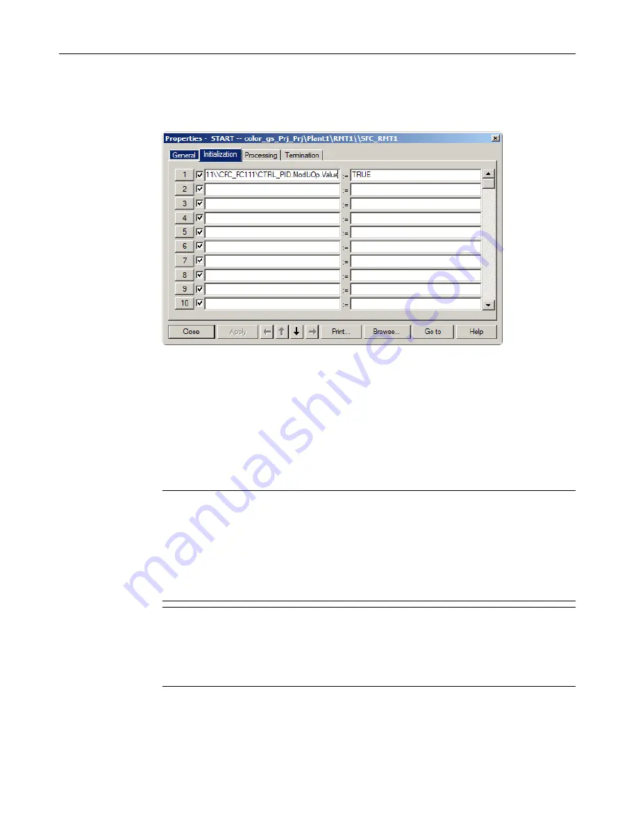
8. Click "Apply".
The value "1" is automatically replaced by "TRUE". The first assignment in the "Start" step
is now complete. The dialog box now appears as follows:
9. Click the number "2" button.
This button appears directly before the statement line. The cursor is then positioned in the
left column of the second line.
10.Repeat steps 3 through 9 to define the remaining addresses for step "START". You will find
the information you require in the below table 'Entries in the "Properties - START" dialog
box'.
11.Click "Apply".
12.Click the arrow button to navigate to the other steps and enter the addresses according to
the tables below.
Note
The addresses in the table are specified in the following format:
[chart folder\chart name\block.I/O].
The"Plant1\RMT1" component is omitted because it is identical for all objects. This keeps
the table easy to understand. As soon as you insert an additional plant or unit in the
"color_gs" project, you must also pay attention to the assignment of the chart to the plant
hierarchy.
Note
When entering the addresses, verify that you have selected the required step based on the
title bar of the "Properties" dialog box.
If you have inadvertently closed the "Properties" dialog box, double click on the step you
are currently editing to reopen the dialog box.
Creating SFCs
7.3 Setting parameters
PCS 7 SMART Getting Started - Part 1 (V9.0 with APL)
Getting Started, 12/2017, A5E42181435-AA
121


