


Controller
6.7 Motor plug
ATE500E
System Manual, 09/2017, A5E33917696-AD
77
6.6.6
Power supply
Slot X3
Function
+
Plus 19.2 … 38VDC
FE
Functional grounding
-
Minus
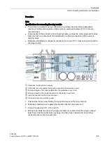
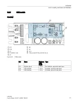
You will find an overview of the slots on the controller in Section Description (Page 22).
6.7
Motor plug
Conductor allocation of the motor plug
Figure 6-8
Conductor allocation of the motor plug
Table 6- 13 Motor plug (slot X7)
Terminal Signal
Description
Cable color
1
VCC (+5 V) Supply voltage for encoder
White, No. 1
2
CH A
Channel A
White, No. 2
3
CH B
Channel B
White, No. 3
4
GND
Ground 5 V voltage supply
White, No. 4
5
MOT_W
Phase W
Black, No. 5
6
FE
Functional grounding
Green, No. 6
7
MOT_V
Phase V
Black, No. 7
8
MOT_U
Phase U
Black, No. 8
You will find an overview of the slots on the controller in Section Description (Page 22).
Содержание SIDOOR ATE500E
Страница 1: ......
Страница 53: ...Controller 6 4 Operation and parameter assignment ATE500E System Manual 09 2017 A5E33917696 AD 53 ...
Страница 54: ...Controller 6 4 Operation and parameter assignment ATE500E 54 System Manual 09 2017 A5E33917696 AD ...
Страница 56: ...Controller 6 4 Operation and parameter assignment ATE500E 56 System Manual 09 2017 A5E33917696 AD ...
Страница 57: ...Controller 6 4 Operation and parameter assignment ATE500E System Manual 09 2017 A5E33917696 AD 57 ...
Страница 58: ...Controller 6 4 Operation and parameter assignment ATE500E 58 System Manual 09 2017 A5E33917696 AD ...
Страница 95: ...Motor 7 2 Installation ATE500E System Manual 09 2017 A5E33917696 AD 95 ...


