Controller
6.6 Connecting terminals and interfaces
ATE500E
68
System Manual, 09/2017, A5E33917696-AD
Task
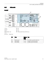
The relay module's relay contacts can be used to report the following door states to the
higher-level controller:
Table 6- 9
Door states
Relay contact
Function
X11
The door has reached the "CLOSED" position
The relay switches on when the controller has detected the CLOSED position and the incremental
sensor ceases to output pulses, i.e. the door is stationary. Pin 3 is connected to pin 1 until the dis-
tance to the CLOSED position is greater than 1 cm in the OPEN direction. The relay then drops out
again immediately, and Pin 3 is once again connected to Pin 2.
X12
Door reverses because of an obstruction, interruption of the light barrier or an opening command.
The relay switches on when the door reverses because of an obstruction, interruption of the light
barrier or an opening command. Pin 1 is then connected to Pin 3 until the OPEN position is reached.
X13
The door has reached the "OPEN" position.
The relay switches on when the distance of the door from the OPEN position falls below 1 cm. Pin 1
and Pin 3 are then connected. The relay drops out immediately as soon as the distance exceeds 1
cm again, and Pin 3 is once again connected to Pin 2.
WARNING
Risk of injury
The door controller is not a safety mechanism. Therefore the relay contacts must not be
used for the elevator safety circuit.
Connection
DANGER
Risk of injury from dangerous electrical voltages
•
When the housing cover of the controller is open, only a safety extra-low voltage of less
than 42 V may be present.
•
Use the protective cover provided for the relay module, and ensure that it is attached
and firmly screwed in place prior to commissioning of the controller.
•
The relay module must not be wired while a voltage is applied!
•
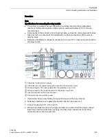
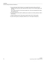
Please follow the procedures described below for connecting a relay module.
Содержание SIDOOR ATE500E
Страница 1: ......
Страница 53: ...Controller 6 4 Operation and parameter assignment ATE500E System Manual 09 2017 A5E33917696 AD 53 ...
Страница 54: ...Controller 6 4 Operation and parameter assignment ATE500E 54 System Manual 09 2017 A5E33917696 AD ...
Страница 56: ...Controller 6 4 Operation and parameter assignment ATE500E 56 System Manual 09 2017 A5E33917696 AD ...
Страница 57: ...Controller 6 4 Operation and parameter assignment ATE500E System Manual 09 2017 A5E33917696 AD 57 ...
Страница 58: ...Controller 6 4 Operation and parameter assignment ATE500E 58 System Manual 09 2017 A5E33917696 AD ...
Страница 95: ...Motor 7 2 Installation ATE500E System Manual 09 2017 A5E33917696 AD 95 ...

