Power supply
8.4 SIDOOR TRANSFORMER UL
ATE500E
System Manual, 09/2017, A5E33917696-AD
133
8.4.4
Test voltage
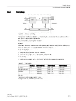
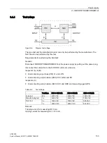
Figure 8-8
Diagram test voltage
The type test and the manufacturing test can only be performed by the manufacturer. The
field can also be performed by the user.
Requirements for performing the field test:
General
Disconnect SIDOOR TRANSFORMER from the power supply by pulling out the power plug,
disconnect the connection to the SIDOOR control circuit device.
Inspection (A) & (B)
●
Interconnecting input lines (PRI) L1 and L2/N
●
Interconnecting output cables (SEC) VCC, GND and PE
Inspection (C)
●
Interconnecting output cables (SEC) VCC and GND and measuring against PE
Table 8- 2
Test voltage
Test time
PRI<->SEC (A)
PRI<->PE (B)
SEC<->PE (C)
Type test
60 s
4000 VAC
4000 VAC
1500 VAC
Manufacturing test
1 s
4000 VAC
4000 VAC
1500 VAC
Field test
1 s
1500 VAC
1500 VAC
350 VAC
1 s
2250 VDC
2250 VDC
500 VDC
Remark:
Tripping current for measuring DC: 0 mA
tripping current for measuring AC: <100 mA
Содержание SIDOOR ATE500E
Страница 1: ......
Страница 53: ...Controller 6 4 Operation and parameter assignment ATE500E System Manual 09 2017 A5E33917696 AD 53 ...
Страница 54: ...Controller 6 4 Operation and parameter assignment ATE500E 54 System Manual 09 2017 A5E33917696 AD ...
Страница 56: ...Controller 6 4 Operation and parameter assignment ATE500E 56 System Manual 09 2017 A5E33917696 AD ...
Страница 57: ...Controller 6 4 Operation and parameter assignment ATE500E System Manual 09 2017 A5E33917696 AD 57 ...
Страница 58: ...Controller 6 4 Operation and parameter assignment ATE500E 58 System Manual 09 2017 A5E33917696 AD ...
Страница 95: ...Motor 7 2 Installation ATE500E System Manual 09 2017 A5E33917696 AD 95 ...


