


Controller
6.6 Connecting terminals and interfaces
ATE500E
74
System Manual, 09/2017, A5E33917696-AD
Wiring and connecting
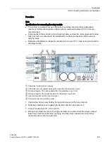
DANGER
Risk of injury due to electrical voltages
The protective cover has to be removed to connect the CAN cable or to activate/deactivate
the terminating resistor.
Perform the following protective measures before removing the protective cover:
•
Disconnect the controller from all live cables.
•
By grounding, ensure that the user/fitter, the controller and other conductors have the
same voltage potential.
Observe the general ESD guidelines.
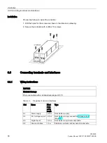
Wiring
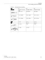
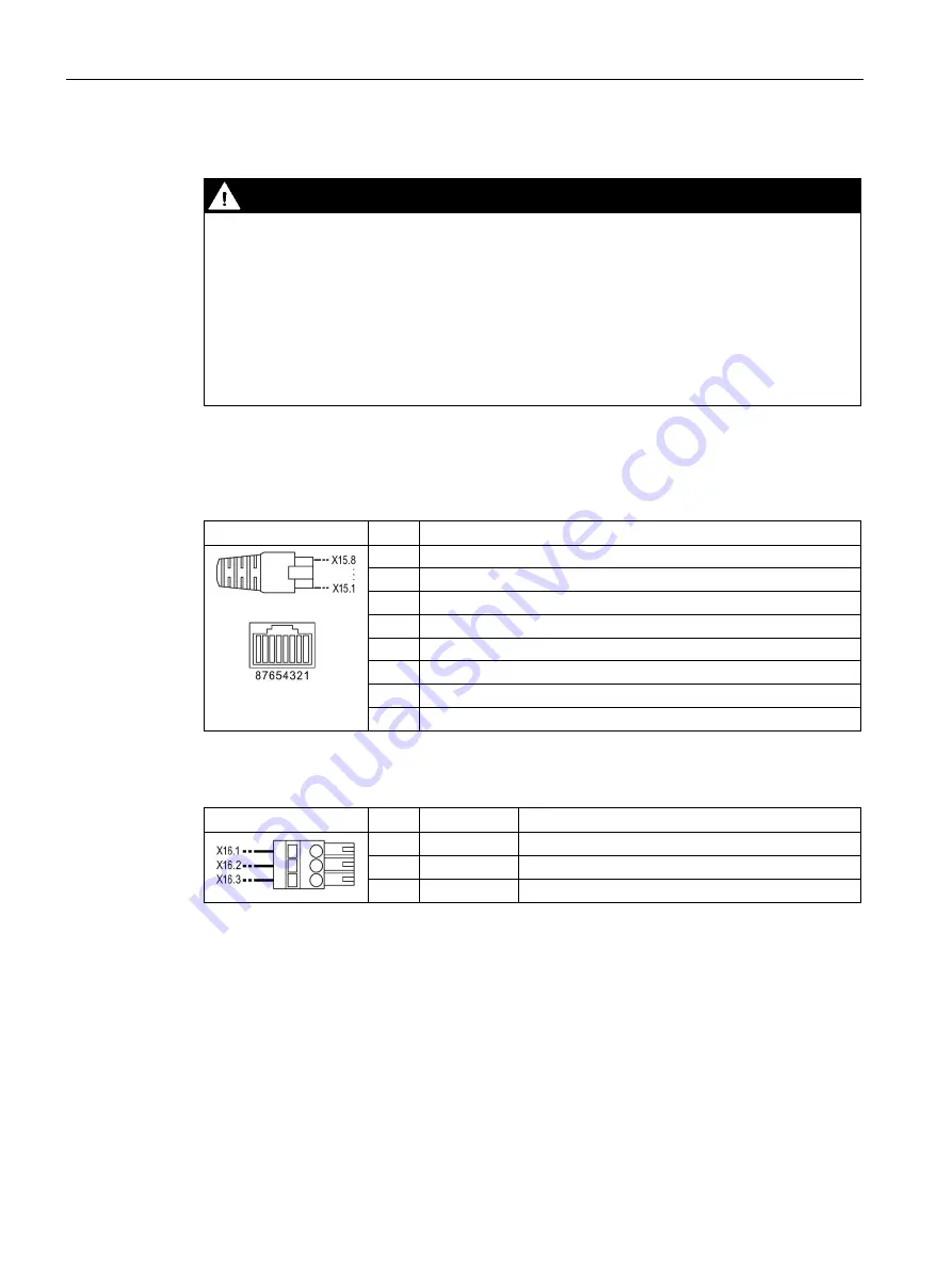
Table 6- 10 Connector X15
Pin assignment
Pin
Signal
1
CAN_H
2
CAN_L
3
GND
4
–
5
–
6
Shield
7
GND
8
–
Table 6- 11 Connector X16
Pin assignment
Pin
Signal
Description
1
CAN_H
CAN high bus cable
2
Shield
CAN cable shield
3
CAN_L
CAN low bus cable
Содержание SIDOOR ATE500E
Страница 1: ......
Страница 53: ...Controller 6 4 Operation and parameter assignment ATE500E System Manual 09 2017 A5E33917696 AD 53 ...
Страница 54: ...Controller 6 4 Operation and parameter assignment ATE500E 54 System Manual 09 2017 A5E33917696 AD ...
Страница 56: ...Controller 6 4 Operation and parameter assignment ATE500E 56 System Manual 09 2017 A5E33917696 AD ...
Страница 57: ...Controller 6 4 Operation and parameter assignment ATE500E System Manual 09 2017 A5E33917696 AD 57 ...
Страница 58: ...Controller 6 4 Operation and parameter assignment ATE500E 58 System Manual 09 2017 A5E33917696 AD ...
Страница 95: ...Motor 7 2 Installation ATE500E System Manual 09 2017 A5E33917696 AD 95 ...


