Connection
6.3 Connecting the control circuit
82
Manual, 08/2017, L1V30368969104A-02
6.3.3.1
Installing auxiliary switches 250 A to 630 A
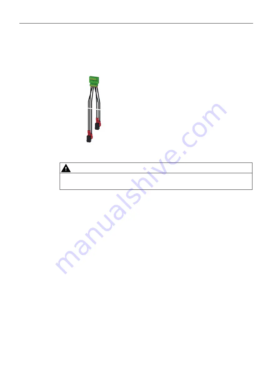
The scope of supply of the 3KC9803-1 auxiliary switch includes the auxiliary switch with
connected plug and the bolts required for mounting.
You can install no more than 2 auxiliary switches one above the other.
Figure 6-64 3KC9803-1 auxiliary switch
WARNING
Hazardous voltage!
Ensure there is no active voltage before beginning to install the auxiliary switches.
Requirements
●
Power supply is switched off
Procedure
1.
Disassemble the motor operator in accordance with the section titled Motor operator
(Page 170).
2.
Place the auxiliary switch at the corresponding position.
Содержание SENTRON
Страница 1: ......
Страница 2: ......
Страница 10: ...Introduction 10 Manual 08 2017 L1V30368969104A 02 ...
Страница 12: ...General information 2 1 Certification 12 Manual 08 2017 L1V30368969104A 02 ...
Страница 20: ...Product information 3 1 Product description 20 Manual 08 2017 L1V30368969104A 02 3KC8 2000 A 2500 A 3200 A ...
Страница 24: ...Product information 3 2 Product family 24 Manual 08 2017 L1V30368969104A 02 ...
Страница 26: ...Functions 26 Manual 08 2017 L1V30368969104A 02 ...
Страница 138: ...Operation 7 4 Automatic mode programming of the electronic module 3KC8 only 138 Manual 08 2017 L1V30368969104A 02 ...
Страница 144: ...Commissioning 8 2 Commissioning the 3KC8 transfer switching equipment 144 Manual 08 2017 L1V30368969104A 02 ...
Страница 176: ...Accessories 9 18 Electronic module 3KC8 only 176 Manual 08 2017 L1V30368969104A 02 ...
Страница 182: ...Service and maintenance 10 2 Regular service and maintenance 182 Manual 08 2017 L1V30368969104A 02 ...
Страница 220: ...Appendix A 3 Storage conditions 220 Manual 08 2017 L1V30368969104A 02 ...


