Connection
6.3 Connecting the control circuit
Manual, 08/2017, L1V30368969104A-02
81
6.3.3
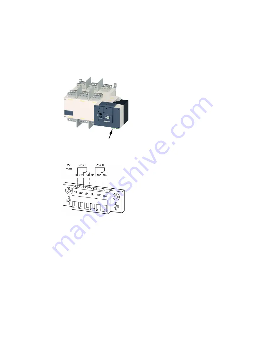
Auxiliary switch of the transfer switching equipment
As well as the named outputs, the transfer switching equipment of sizes 2000 A to 3200 A
contain further outputs of already installed auxiliary switches that indicate switch positions I
and II.
Figure 6-62 Auxiliary switches, current ratings 2000 A to 3200 A
The auxiliary switch has the following outputs:
Figure 6-63 Outputs of the auxiliary switch
The outputs have the same PIN designation twice.
If auxiliary switches in addition to the above listed outputs are required for current ratings
250 A to 1600 A, you can optionally install up to 2 auxiliary switches.
Содержание SENTRON
Страница 1: ......
Страница 2: ......
Страница 10: ...Introduction 10 Manual 08 2017 L1V30368969104A 02 ...
Страница 12: ...General information 2 1 Certification 12 Manual 08 2017 L1V30368969104A 02 ...
Страница 20: ...Product information 3 1 Product description 20 Manual 08 2017 L1V30368969104A 02 3KC8 2000 A 2500 A 3200 A ...
Страница 24: ...Product information 3 2 Product family 24 Manual 08 2017 L1V30368969104A 02 ...
Страница 26: ...Functions 26 Manual 08 2017 L1V30368969104A 02 ...
Страница 138: ...Operation 7 4 Automatic mode programming of the electronic module 3KC8 only 138 Manual 08 2017 L1V30368969104A 02 ...
Страница 144: ...Commissioning 8 2 Commissioning the 3KC8 transfer switching equipment 144 Manual 08 2017 L1V30368969104A 02 ...
Страница 176: ...Accessories 9 18 Electronic module 3KC8 only 176 Manual 08 2017 L1V30368969104A 02 ...
Страница 182: ...Service and maintenance 10 2 Regular service and maintenance 182 Manual 08 2017 L1V30368969104A 02 ...
Страница 220: ...Appendix A 3 Storage conditions 220 Manual 08 2017 L1V30368969104A 02 ...


