


66/166
Siemens Building Technologies
Basic Documentation RVA47.320
CE1P2379E
HVAC Products
Description of the heating engineer settings
15.07.2002
Setpoints .
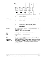
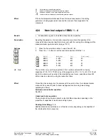
4.12 Outside
temperature
source
•
Display and location of actual outside temperature measurement
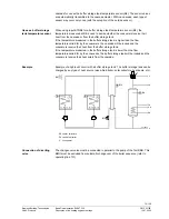
When interconnecting several controllers, only one outside sensor is required. This
sensor will be connected to any of the controllers and delivers its signal via LPB.
The controllers to which no sensor is connected adopt the outside temperature signal
via the bus system, from a controller to which a sensor is connected.
1. Press the operating line selection buttons to select operating line 62.
2. No setting can be made with the + / - buttons.
Display
Unit
– – . – –
00.01...14.16
No signal
Segment and device address
The address of the outside detector that currently delivers the outside temperature
signal will automatically be displayed on this line.
– – . – –
No outside sensor signal
01.02
Address of outside sensor
The first 2 digits represent the segment number (01.)
The second digit corresponds to the device number (.02)
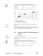
If required (e.g. due to different exposure to solar radiation of the various buildings), the
different sections of the system can be equipped with their own outside sensors.
For more detailed information, refer to section ”Outside temperature source” of ”Local
Process Bus (LPB), Basic Documentation, System Engineering” (document no.
CE1P2370E).
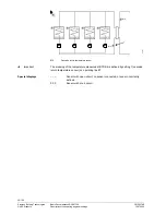
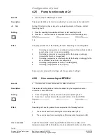
4.13
Boiler temperature setpoint of BMUs
•
Indication of BMU temperature setpoints
•
Better overview of the plant’s operational status
The lowest connected BMU number with the associated temperature setpoint will
automatically be displayed on this line. The temperature setpoints of the other BMUs
used in the cascade can be interrogated by pressing the + / - buttons. Nonexisting
BMUs will be skipped.
1.
Press the operating line selection buttons to select line 65.
2.
Press the + / - buttons to select the setpoint of the required BMU.
Display
Unit
1...4 / 0...140
BMU number / °C
The setpoints can only be displayed but not changed. The function helps better
understand the control sequences taking place in the controller.
No setpoint is displayed (---), when
•
there is no heat demand from the consumers
•
no BMU is connected to the controller
Benefit
Description
Setting
Effect
Display
Note
Benefit
Description
Setting
Note