53/166
Siemens Building Technologies
Basic Documentation RVA47.320
CE1P2379E
HVAC Products
Description of the enduser settings
15.07.2002
3.22
Indication of faults
•
Straightforward checking of plant
•
Fault tracing is made easier
The controller indicates faults that may have occurred in the controller itself or in the
system.
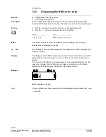
The display shows "Er" if an error has occurred.
1. Press the operating line selection buttons to select line 50.
2. Press the + / - buttons to display the list of faults.
Display
Unit
0...255 -
The first entry in the error list will automatically be displayed on this operating line.
By pressing
, it is possible to switch between error signals.
The controller can store a maximum of 2 error signals. The error signal will be cleared
only after the cause of the fault has been removed. If additional errors are present, they
will be stored as soon as storage capacity becomes available.
Errors that may occur locally on this device:
Display
Description of error
Blank No
error
10
outside temperature sensor
26
Cascade flow temperature sensor
46
Cascade return temperature sensor
50
D.h.w. temperature sensor
58
D.h.w.
thermostat
61
Fault room unit
70
Buffer storage tank temperature sensor
81
Short-circuit
LPB
82
Address collision on LPB (same address several times)
86
Short-circuit
PPS
100
2 clock masters present
145
Wrong device connected to PPS
146
Inadmissible plant configuration
147
No BMU connected
150
General BMU fault
In the case of error code 150, operating line 49 also gives the manufacturer-specific
error code of the BMU.
Benefit
Description
Setting
Effect
Note
Error signals
Device errors
Note


