12
Chapter 5
Communication Protocol
Figure 5.1
i-3 I/O Controller Communication Interface
RS-485
Terminal
Introduction
The i-3 V2 I/O Controller provides
Modbus as the standard communication
protocol. A personal computer or Building
Automation System may be connected to
i-3 V2 I/O Controller using a twisted pair
serial cable wired to RS-485 terminal
located in the communication interface
section of I/O Board.
The i-3 V2 I/O Controller will act as a
Modbus Slave using Modbus RTU or
Modbus TCP/IP (optional) slave protocol
when interfacing with Building
Automation System. Modbus master
devices connected to the controller
can access (read) the data, making
configuration changes and initiating
control actions.
Connecting the controller to a
Modbus System (PC or Building
Automation) system
A twisted pair serial cable is used to
connect the i-3 V2 I/O Controller to a
personal computer or Building Automation
System. RS-485 to RS- 232 conversion
cable is required to connect to a personal
computer. This cable is connected to the
RS-485 terminal which is located in
the I/O Board communication interface
section as shown in
Figure 5.1.
The RS-485 terminal is accessible through
Communication Interface Door without
removing the panel deadfront. See
Figure
3.1
on page 8.
Configuring i-3 V2 I/O Controller
There are two methods of configuring
i-3 V2 I/O Controller: using The Panel
Configurator Software or Modbus
communications.
1. Using the i-3 V2 I/O Configurator
Software
Refer to “i-3 V2 I/O Configurator
Software Tool” section for instructions
on how to download this program from
our Web site.
2. Using Modbus Communication
Assigning a Modbus address
By default, i-3 V2 I/O Controller device
address is assigned as 126. If multiple
i-3 V2 I/O Controllers or other Modbus
devices are present on the same line,
each device must be assigned a unique
device
address.
The Modbus address is programmed
with rotary switches located on the
electronic
board.
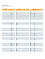
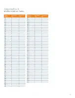
See Appendix A
– Modbus Address
Table for rotary switch settings.
Changing input types
To change input types, follow the steps:
1. Use either function code 6, preset
single register or 16: preset multiple
registers.
2. The register address for input types
ranges from 1792 (for input terminal 1)
to 1811 (for input terminal 20).
3. Assign the desired input type value,
which can be found in the Modbus Map
Table on page 10. For example, input
type “3” is digital input maintain
normally ON switch (2-wire).
Содержание i-3
Страница 1: ...3 User Guide www usa siemens com i 3 i 3 V2 I O Controller Modbus ...
Страница 54: ...52 Appendix E USB to RS485 Converter Driver Software Installation Instructions ...
Страница 57: ...55 Appendix F Recommended Input Devices ...
Страница 58: ...56 Appendix F Recommended Input Devices ...
Страница 59: ...57 Appendix F Recommended Input Devices ...
Страница 60: ...58 Appendix F Recommended Input Devices ...
Страница 61: ...59 Appendix F Recommended Input Devices ...
Страница 62: ...60 Appendix F Recommended Input Devices ...
Страница 63: ...61 Appendix F Recommended Input Devices ...
Страница 64: ...62 Appendix F Recommended Input Devices ...
Страница 65: ...63 Appendix F Recommended Input Devices ...
Страница 66: ...64 Appendix F Recommended Input Devices ...
Страница 67: ...65 Appendix F Recommended Input Devices ...
Страница 68: ...66 Appendix F Recommended Input Devices ...
Страница 69: ...67 Appendix F Recommended Input Devices ...
Страница 70: ...68 Appendix F Recommended Input Devices ...
Страница 71: ...69 Appendix F Recommended Input Devices ...
Страница 72: ...70 Appendix F Recommended Input Devices ...
Страница 73: ...71 Appendix F Recommended Input Devices ...
Страница 74: ...72 Appendix F Recommended Input Devices ...
Страница 75: ...73 Appendix G Common Networking Setups ...
Страница 76: ...74 Appendix G Common Networking Setups ...
Страница 78: ...76 Notes ...
Страница 79: ......


