background image

8 – 4

3ZW1012-0WL11-0AB1

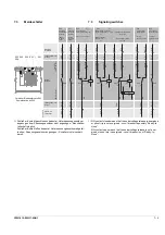
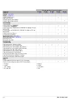
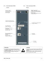
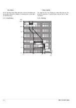
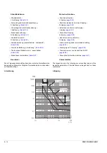
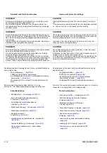
Einstellen des Überstromschutzes

Die Einstellung aller Parameter erfolgt mit Drehkodierschaltern.

Schutzfunktionen


Überlastschutz – 

 L-Auslösung 

(page 8-22)


Kurzverzögerte Kurzschlussauslösung – 

 S-Auslösung 

(Seite 8-22)

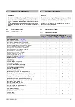
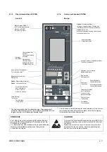
VORSICHT

CAUTION 

Parametereinstellungen grundsätzlich nur vornehmen, wenn 

der Leistungsschalter ausgeschaltet ist.

Eine Veränderung der Parameter bei eingeschaltetem Lei-

stungsschalter kann zu ungewolltem Auslösen des Leistungs-

schalters führen.

Adjust parameters only when the circuit-breaker is switched 

off. 

If the parameters are modified with the circuit-breaker switched 

on, this can trip the circuit-breaker unintentionally.

VORSICHT

CAUTION 

Bei der Anlagenprojektierung und Selektivitätsbetrachtung ist 

sicherzustellen, dass der Leistungsschalter nicht Ströme führen 

kann, die oberhalb der im Katalog angegebenen Schaltleistungs-

werte liegen.

Übergeordnete Schutzgeräte sind so einzustellen, dass diese 

Fehlerfälle sicher abgeschaltet werden.

When planning a project and considering selectivity it has to be 

ensured loads carried by the circuit-breaker will not exceed the 

breaking capacity stated in the 3WL catalogue. 

Upstream protection equipment has to be set in a way, that 

these faults are interrupted safely.

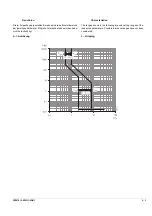
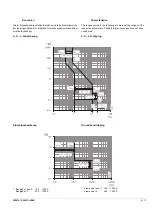
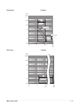
Der Wert 0,1 ist eingestellt,

wenn der Drehschalter

in diesem 

Drehwinkelbereich

 steht

The value 0.1 is set if the

rotary switch is positioned in this 

zone

3 x 0,5

Overcurrent protection settings

All parameters are adjusted with rotary coding switches.

Protective functions


Overload protection – 

 L-tripping

(page 8-22)


Short-time-delayed short-circuit tripping –

 S-tripping

(page 8-22)

Содержание 3ZW1012-0WL11-0AB1

Страница 1: ...che elektrische Spannung Kann Tod schwere Personenschäden sowie Schäden an Geräten und Ausrüstung bewirken Vor dem Arbeiten an diesem Gerät Anlage unbedingt spannungsfrei schalten Gefahr bei gespanntem Federspeicher Federspeicher entspannen Hazardous voltage Will cause death serious personal injury or equip ment damage Disconnect power before working on this equipment Danger if spring is charged D...

Страница 2: ...n Sichtprüfung Visual examination Haken hook Schrauben Steckschlüssel mit Schlüsselweite wrench with size in mm Schlitzschraubendreher Slotted type screwdriver Kreuzschlitzschraubendreher Philips PH PoziDriv PZ Cruciform screwdriver Philips PH PoziDriv PZ Torx Schraubendreher T Torx screwdriver T Innensechskant Schraubendreher Hexagon socket screwdriver Anzugsdrehmoment Tightening torque 1 Nm 0 74...

Страница 3: ... H HFXWDU TXDLVTXHU WUDEDOKRV QR DSDUHOKR 9ROWH D FRORFDU WRGDV DV FREHUWXUDV DQWHV GH YROWDU D OLJDU DV IRQWHV GH DOLPHQWDomR 7HKOLNHOL JHULOLP gO P WHKOLNHVL YH D Dù U DUDODQPD WHKOLNHVL PHYFXWWXU LKD GD oDO üPDODU DS OPDGDQ QFH W P J o ND QDNODU NDSDW OPDO YH ELU DoPD HPQL HWL OH GRQDW OPDO G U o ND QDNODU WHNUDU Do OPDGDQ QFH W P NDSDNODU HUOHULQH WDN OPDO G U 7 1d 2 127 LQVWDODomR H PDQXWHQom...

Страница 4: ...ǀƮ ƽƼǀƼlj ƲƺƲƽưƼ ƼƶƫƿƲǀƲ ǀƴƺ ǀƽƼǂƼƱƼƿƬƮ ǀƴƾ ƿǁƿƷƲǁƫƾ ƹƲ ƲƺƪƽưƲƶƮ 9ROWDV FRQW LUWHDFK DRO JR EKIDLJKIHDU EiV Qy WURPJKRUW 0 FK JDFK FXPKDFKW D VKROiWKUDtRQQ DQ JOpDV VHR DJXV JODViLO DPDFK t URLPK REDLU D GKpDQDPK DU DQ QJOpDV VHR XLU QD FO GDLJK DU IDG DU DLV URLPK DQ JFXPKDFKW D VKROiWKUDtRQQ DQ JOpDV VHR D FKXU DU VL O DUtV ƞƟƝƠƝƤƊ Ð 5 ƕ ƲưƷƮǀƩƿǀƮƿƴ ƷƮƶ ƿǁƺǀƫƽƴƿƴ ƽƪ Ʋƶ ƺƮ ƱƶƲƻƩưƼƺǀƮƶ Ʈ Lj ƲƻƲƶƱƶƷƲ...

Страница 5: ...ichnungen in dieser Dokumentation können Marken sein deren Benutzung durch Dritte für deren Zwecke die Rechte der Inhaber verletzt VORSICHT CAUTION Zum Schutz der elektrostatisch gefährdeten Bauele mente EGB ist der Schalter anzuschließende Geräte und das Bedienpersonal auf das gleiche Potenzial zu bringen To protect the electrostatic sensitive devices ESD the circuit breaker equipment to be conne...

Страница 6: ...halter Kodierung Hilfsstromstecker Messerleiste 5 19 Hilfsstromstecker aufsetzen 5 19 0 5 Table of contents Symbols 0 II Safety instructions 0 III Security information 0 V Note regarding the manuals scope 0 V Table of contents 0 VI 1 Design 1 1 Circuit breaker 1 1 Guide frame 1 2 2 Labels 2 1 Circuit breaker options label 2 1 Rating Plug label 2 1 Type label circuit breaker 2 2 Type label guide fr...

Страница 7: ...ctive functions 8 4 Characteristics 8 5 Overcurrent release ETU25B 8 6 Design 8 6 Overcurrent protection settings 8 7 Protective functions 8 7 Characteristics 8 8 Overcurrent release ETU27B 8 9 Unzulässige Bereiche für Leitungen 5 20 Leitungsverlegung am Einschubrahmen 5 20 Bestückung mit Hilfsleiteranschlüssen 5 21 Bestellnummern 5 21 Schutzleiter anschließen 5 22 Festeinbauschalter 5 22 Einschub...

Страница 8: ...US 8 123 Übersetzungsverhältnis und Bestellnummer 8 124 Kundenseitige Beistellung der Spannungswandler 8 124 Design 8 9 Overcurrent protection settings 8 10 Protective functions 8 10 Characteristics 8 11 Overcurrent release ETU45B 8 12 Design 8 12 Overcurrent protection settings 8 13 Protective functions 8 14 Characteristics 8 14 Overcurrent release ETU76B 8 17 Design 8 17 Overcurrent protection s...

Страница 9: ...ectrical function test 10 7 Closing coil 10 7 Shunt trip 10 8 Undervoltage release 10 8 Externer G Wandler 8 125 Beispiele 8 125 Anschließen 8 125 Externe Spannungsversorgung 8 126 Anschluss 8 126 Anforderungen 8 126 Bestellnummer 8 126 Handprüfgerät 8 127 Ansicht 8 127 Vorbereitende Arbeiten 8 127 Spannungsversorgung 8 128 Netzspannung umschalten 8 128 Anschließen 8 128 Bedienung 8 130 Prüfen der...

Страница 10: ...ffnung in Schaltschranktür bohren 14 13 Sicherheitsschloss Handkurbel nachrüsten 14 14 Updating the options label 10 8 Order numbers Z options 10 9 Capacitor Energy Storage Unit for shunt release 10 11 Technical data 10 11 Installation 10 11 Order numbers 10 12 11 Auxiliary and control switches 11 1 Signaling switches 11 1 Mounting signaling switches 11 1 Contact position driven switches 11 2 Snap...

Страница 11: ...ng on circuit breaker 17 9 Fitting coding on guide frame 17 10 Schlossbaugruppe vormontieren 14 15 Einbau 14 15 Feld aus Bedienpult ausbrechen 14 16 Sicherheitsschloss Mechanisch AUS nachrüsten 14 16 Sicherheitsschloss Rücksetzknopf nachrüsten 14 17 Abschließen 14 18 Schilder aktualisieren 14 18 Ausstattungsschild des Leistungsschalters 14 18 Typschild Einschubrahmen 14 18 Bestellnummern Z Option ...

Страница 12: ...hutzabdeckung 22 2 Handhabung 22 2 Order number 17 10 Coding variants 17 11 Position signaling switches for guide frame 17 15 Terminals 17 15 Circuit Breaker position and contact state 17 16 Installation 17 16 Updating the type label 17 17 Order numbers Z options 17 17 18 Mutual mechanical circuit breaker interlocking 18 1 Mutual mechanical interlocking module 18 1 Version 1 18 2 Version 2 18 2 Fi...

Страница 13: ... 28 1 Checklists 28 1 Announcement of circuit breaker modification 28 3 SENTRON 3WL1 ETU settings 28 5 Contact 28 6 Bestellnummer 22 2 Ausführung mit Kunststoffscharnieren 22 3 Maßbild für Türausschnitt und Befestigungsbohrungen 22 3 Anbau der Schutzabdeckung 22 4 Handhabung 22 4 Bestellnummer 22 4 23 Wartung 23 1 Vorbereitung von Wartungsarbeiten 23 3 Schalter ausschalten und Federspeicher entspa...

Страница 14: ...nummer Bezeichnung 3WL921_ _F_ _ _ _ _ _ _ 3WL921_ _G_ _ _ _ _ _ _ 3WL921_ _H_ _ _ _ _ _ _ 3WL921_ _I_ _ _ _ _ _ _ Note for use These operating instructions are suitable for circuit breakers with the order number designation 3WL1_ _ _ _ _ _6_ _ _ _ _ 3WL1_ _ _ _ _ _7_ _ _ _ _ These operating instructions are suitable for guide frames with the order number designation 3WL921_ _F_ _ _ _ _ _ _ 3WL921...

Страница 15: ...3ZW1012 0WL11 0AB1 0 XV ...

Страница 16: ... 26 Locking device OFF option 27 Front panel 28 Receptacle for auxiliary contacts according to equipment 1 Aufbau 1 1 Leistungsschalter 1 Lichtbogenkammer Seite 23 5 2 Tragegriff 3 Kennzeichnungsschilder 4 Motorabstellschalter Option Seite 12 3 oder Elektrisch EIN S10 Option Seite 10 4 5 Typschild Leistungsschalter Seite 2 1 6 Speicherzustandsanzeige Seite 6 6 7 Taster Mechanisch EIN 8 max Schalte...

Страница 17: ...r Option 17 Positionsmeldeschalter Option 18 Schleifkontaktmodul Hilfsleiter Anzahl ausstattungsabhängig 0072 01a 10 11 12 13 14 15 16 17 18 1 2 Guide frame 1 Arc chute cover option 2 Arcing openings 3 Hole for crane hook page 4 2 4 Shutter option 5 Locking device shutter option 6 Type label guide frame page 2 2 7 Disconnecting contacts 8 Earthing terminal 14 mm page 5 22 9 Locking device guide ra...

Страница 18: ...Z 3WL1 232 4CB35 4GG2 Z 0131 ___1 Hauptstrombahnen Main conducting path Bestell Nr Leistungsschalter Order no circuit breaker Ergänzung der Bestell Nr weitere Optionen Supplement order no further options Zweiter Spannungsauslöser F2 oder Unterspannungsauslöser F3 oder F4 Second shunt trip F2 or undervoltage release F3 or F4 Hilfskontakte Auxiliary contacts Rücksetzmagnet Remote reset coil Einschal...

Страница 19: ...messungsbetriebsspannung Rated operational voltage Bemessungskurzzeitstromfestigkeit Rated short time withstand current Trennfunktion Disconnecting function Bemessungsisolationsspannung Rated insulation voltage Hinweis für Einsatz in IT Systemen Direction for use in IT systems Ident Nr Leistungsschalter circuit breaker ID Approbation Approval Bemessungsnennstrom des Einschubrahmens Guide frame max...

Страница 20: ...rsonnel should work on this equipment after becoming thoroughly familiar with all warnings safety notices and maintenance procedures contained herein and on the devices Successful and safe operation of this equipment is dependant on proper handling installation operation and maintenance Qualifiziertes Personal Qualified Person im Sinne dieser Bedienungsanleitung bzw der Warnhinweise auf dem Produk...

Страница 21: ...sand nur in der Originalverpackung Feuchtigkeitsanzeigeschild überprüfen Check humidity indicator Weitere Lagerung Further storage Rosa Pink Blau Blue Trockenmittel erneuern oder trocknen Kunststofffolie dicht verschweißen Verpackung regelmäßig überprüfen Renew or dry desiccant Reseal the plastic sheeting Check packing from time to time Dichteverpackung unwirksam Schalter auf Korrosionsschäden prü...

Страница 22: ...el Follow instructions for use of lifting bar assembly Use OSHA NIOSH approved rigging equipment and personal protection equipment for lifting moving the circuit breakers and guide frames Vorsicht Caution Schalter Breaker Einschubrahmen Guide frame Schalter Einschubrahmen Breaker Guide frame Nicht auf die Rückseite legen Do not place breaker on its rear side Baugröße Polzahl Frame size No of poles...

Страница 23: ...on observance can result in death severe personal injury or substantial property damage GEFAHR DANGER Schweres Gerät Falsches Kranen kann Tod schwere Personenschäden sowie Schäden an Geräten und Ausrüstung bewirken Niemals einen Leistungsschalter Kurzschließ Erdungs und Überbrückungseinschub oder Einschubrahmen über Personen heben Bedienungshinweise zum Kranen beachten Nur OSHA NIOSH geprüftes Kra...

Страница 24: ...0 8 8 Muttern Spannscheiben 4 bolts M10 8 8 nuts conical spring washers Setzmutter Non removable nut 4 Schrauben M8 8 8 Spannscheiben 4 bolts M8 8 8 conical spring washers 5 1 2 Einbau auf waagerechter Ebene Werden in Schaltschränken ohne Fachböden mehrere Einschub schalter übereinander angeordnet empfehlen wir Lichtbogen kammerabdeckungen zu verwenden 5 1 3 Einbau an senkrechter Ebene mit Tragwin...

Страница 25: ...G I FS I 3 pol 4 pol 300 390 338 428 BG II FS II 3 pol 4 pol 440 570 478 608 Bestellnummer Order number Tragwinkel Bracket angle 3WL9111 0BB50 0AA0 b c Darstellung für Baugröße II mit Frontanschluss Representation for frame size II with front connection ...

Страница 26: ...indestquerschnitte der anlagenseitigen Anschluss schienen sind in IEC 60947 und Katalog LV 10 angegeben 5 2 1 Horizontalanschluss Der Horizontalanschluss ist Standardanschluss für Festeinbau schalter und Einschubrahmen Nur für Einschubrahmen Einbau des Horizontalanschlusses beim Umrüsten Seite 5 9 5 2 2 Flanschanschluss nur Einschubrahmen Der Einbau der Flanschanschlüsse erfolgt wie der Einbau der...

Страница 27: ...g bar 5 2 3 Frontanschluss Festeinbauschalter Ausführung der Anschlussschienen 1 Standardausführung 2 Ausführung nach DIN 43673 Doppellochreihe 3 Bohrungen Ø 13 5 Befestigung der Anschlussschienen 1 Für Baugröße I 1000 A und II 2000 A 2 Für Baugröße I 1250 A 2000 A Schaltvermögen H II 2500 A 3200 A III 4000 A 3 Lange Anschlussschiene 4 Kurze Innensechskantschraube ISO 4762 M6 mit Spannscheibe 5 Ku...

Страница 28: ...n schluss erfordert vorher Einbau des Horizontalanschlusses Seite 5 8 1 3 4 2 5 85 Nm 85 Nm 1 2 3 4 5 5 Gr Size 5 Gr Size 8 Nm 8 Nm Guide frame Two variations are offered 1 Standard version 2 Version according to DIN 43673 double hole row 3 Slots for phase separation walls mounting position as shown 4 Support 5 Holes Ø 13 5 Fastening connecting bars 1 For frame size I 1000 A and II 2000 A 2 For fr...

Страница 29: ...utter Spannscheiben oben unten 1 x M12 8 8 nut conical spring washers top bottom 1000 A 1250 A 2000 A 1 Schaltvermögen H1 breaking capacity H1 II 3 x Ø 13 5 mm 85 Nm 2500 A 1 3200 A Baugröße Frame size Bemessungsnennstrom Rated current 3 x M12 8 8 Muttern Spannscheiben oben unten 3 x M12 8 8 nuts conical spring washers top bottom 1 1 Anschlussschiene pro Hauptanschluss mittig befestigt s Bild für ...

Страница 30: ... Bemessungsnennstrom Rated current 2 x Ø 13 5 mm 3 x Ø 13 5 mm 4 x Ø 13 5 mm 1000 A 1200 A 2000 A Schaltvermögen H breaking capacity H M6 Schrauben Mut tern und Scheiben M6 bolts nuts and washers 2 x M 6 Setzmutter press nut 1 x M 6 Setzmutter press nut I II III Vertikalanschlüsse links und rechts asymmetrisch Vertical terminals left and right asymmetrical Baugröße Frame size Bemessungsnennstrom R...

Страница 31: ... ist spiegelbildlich zu montieren Picture shows upper vertical terminal bottom must be assembled inversly Hinweis Note Die Lamellenblöcke für Leistungsschalter der Baugröße III 4000 A sind nicht vollständig mit Lamellen bestückt Achtung Bei der Montage nur gleichartig ausgestattete Lamellenblöcke verwenden The finger cluster for circuit breaker frame size III 4000 A are not fully equiped with cont...

Страница 32: ...r circuit breaker 5 2 5 Zulässige Anschlussschienen Varianten für Baugröße I 1000 V DC Leistungstrennschalter Baugröße I 1000 V DC Leistungstrennschalter werden nur in vier poliger Ausführung angeboten Plus Minuspol des in Reihe zu ver schaltenden Leistungstrennschalters bilden die außenliegenden jeweils oberen Anschlüsse der Phasen N und L3 Verfügbare Schie nenvarianten für diese beiden Anschlüss...

Страница 33: ... 1000 A 1 3WL9111 0AL07 0AA0 Schaltvermögen breaking capacity H 1250 A 2000 A 1 3WL9111 0AL08 0AA0 II 2000 A 1 3WL9111 0AL11 0AA0 2500 A 1 3WL9111 0AL12 0AA0 3200 A 1 3WL9111 0AL13 0AA0 III 4000 A 1 3WL9111 0AL14 0AA0 Frontanschluss einfach unten Front connection single hole bottom I 1000 A 1 3WL9111 0AL51 0AA0 1250 A 1600 A 1 3WL9111 0AL52 0AA0 II 2000 A 1 3WL9111 0AL53 0AA0 2500 A 1 3WL9111 0AL5...

Страница 34: ...0 A 2000 A 1 3WL9111 0AN16 0AA0 Schaltvermögen breaking capacity C 1600 A 3200 A 1 3WL9111 0AN38 0AA0 II 2000 A 1 3WL9111 0AN17 0AA0 2500 A 1 3WL9111 0AN18 0AA0 3200 A 1 3WL9111 0AN21 0AA0 III 5000 A 1 3WL9111 0AN22 0AA0 6300 A 3 polig oben unten 3 pole above below 1 Satz Set 3WL9111 0AN23 0AA0 6300 A 4 polig oben 4 pole above 1 Satz Set 3WL9111 0AN20 0AA0 6300 A 4 polig unten 4 pole below 1 Satz ...

Страница 35: ...mmen Das Anschließen von Kabeln unmittelbar an die Leistungs schalteranschlüsse ist nicht zulässig On 4 pole circuit breakers the neutral conductor must always be connected all on the left Otherwise this can cause malfunctions of the electronic over current release The connection of cables directly to the circuit breaker termi nals is not permitted Schalter Breaker Metallspäne entfernen Remove swa...

Страница 36: ...ter abstützen für Schaltvermögen N S H BG II Schaltvermögen C Ics Icu 100 kA BG III Schaltvermögen C Ics Icu 100 kA Hinweis Note Die Hauptleiter für BG II Schaltvermögen C Ics Icu 100 kA sind in vertikaler und horizontaler Richtung abzustützen The main conductors for FS II breaking capacity C Ics Icu 100 kA must be braced in vertical and horizontal direction 100 100 100 ...

Страница 37: ...ferrule 1 Schraublose Anschlusstechnik Screwless terminal system 0 5 2 5 mm2 AWG 20 14 Aderendhülse 2 Wire end ferrule 2 0 5 2 5 mm2 AWG 20 14 Aderendhülse 2 Wire end ferrule 2 Vormontierte Leitungen Pre assembled wires AWG 14 Länge length 1 m 40 Ringösen Schraubtechnik Ring lug system 7 mm 7 mm Empfehlung AMP Reihe PIDG AWG 16 14 Bestell Nr 50881 Recommendation AMP PIDG series AWG 16 14 order no ...

Страница 38: ... Ausführung und BG II Schaltvermögen C 3 Messerleistenadapter für hohe Lichtbogenkammer X5 X6 X8 1 2 X7 COM 0173 06 1 2 1 2 3 4 0173 09 3 5 6 0 7 Nm PH 1 5 4 2 Receptacle Arrangement 1 Arc chute 2 Receptacle Retrofitting 1 Blanking cover 2 Receptacle Only for circuit breaker 1000 V version and FS II breaking capacity C 3 Receptacle adapter for high arc chute ...

Страница 39: ...benötigen keinen Hilfsstromstecker Die Leitungen werden direkt am Schleifkontaktmodul angeschlossen 3 0 x 0 6 1 2 1 2 0769 3 0 x 0 6 0 5 Nm Connecting secondary wiring Screwless terminal system 5 4 3 Sliding contact module Retrofitting 1 Cradle with sliding contact modules 2 Sliding contact module For the SIGUT terminal system a one piece sliding contact module is also available The one piece slid...

Страница 40: ...szungen anbringen 1 Rückseite Hilfsstromstecker 2 Führungszungen 3 0 x 0 6 1 0 5 Nm PH 1 2 3 4 3 0 x 0 6 5 6 0 5 Nm 0 5 Nm Länge 1 m Lenght 40 1 2 5 4 4 Auxiliary connectors Versions 1 SIGUT system 2 Ring lug system 3 Insulated ring lug 4 Screws ANSI B 18 6 3 4 5 Screwless terminal system 2 terminals in parallel per contact 6 Fixed mounted breaker only pre assembled wires Fixed mounted breaker onl...

Страница 41: ...or 2 Fixed mounted breaker Breaker secondary disconnect block Draw out circuit breaker Guide frame secondary disconnect block Nur Festeinbauschalter Kodierung Hilfsstromstecker Messerleiste 1 Nut 2 Führung 3 Modulbezeichnung hier X5 muss nach vorn zeigen 4 Modul X5 Hilfsstromstecker aufsetzen L 1 Hilfsstromstecker 2 Festeinbauschalter Messerleiste Einschubschalter Schleifkontaktmodul 0100 01_nu X5...

Страница 42: ... Wiring in guide frame 5 4 5 Unzulässige Bereiche für Leitungen 1 Ausblasraum 2 Tragegriff 3 Ausblasöffnungen 4 Verriegelungen Sind Lichtbogenkammerabdeckungen vorhanden dürfen die Hilfsleiter nicht auf diesen Abdeckungen verlegt werden 5 4 6 Leitungsverlegung am Einschubrahmen VORSICHT CAUTION Unzulässige Bereiche für Leitungen Leitungen können beschädigt werden Impermissible area for wires Damag...

Страница 43: ...sauslöser S23 Trip signaling switch S24 Signaling switches storage spring charged S21 Electrical ON push button S10 Signaling switches 1st auxiliary release S22 Signaling switches 2nd auxiliary release S23 X8 Überstromauslöser ETU 45B ETU76B interner c Anschlüsse für externen Stromwandler für Überlastungs schutz im N Leiter und Erdschlussschutz Stromwandler im N Leiter eingebaut Stromwandler im St...

Страница 44: ...en Bei BG II 4000 A wird der Einschubrahmen nur durch die Schrau ben zur Befestigung im Schaltschrank geerdet 14 mm 14 mm 5 5 Connecting the grounding conductor 5 5 1 Fixed mounted breaker 5 5 2 Guide frame The guide frame of FS II 4000 A is grounded only by the screws fastening it in the cubicle ...

Страница 45: ... x hexagon socket thin head cap screw M6 x 12 DIN 6912 2 Back of the guide frame 3 Contact module 4 Grounding connection 5 6 Erdschutz zwischen Einschubrahmen und Einschubschalter Nicht zulässig bei BG II Schaltvermögen C 1 Einschubrahmen 2 Kontaktmodul für Einschubrahmen 3 Rückseite des Einschubschalters 4 Kontaktmodul für Einschubschalter 5 6 1 Nachrüsten Anbau des Kontaktmoduls am Einschubrahme...

Страница 46: ...r BG III 3 polig draw out circuit breaker frame size III 3 pole 3WL9111 0BA07 0AA0 Einschubschalter BG I 4 polig draw out circuit breaker frame size I 4 pole 3WL9111 0BA08 0AA0 Einschubschalter BG II 4 polig draw out circuit breaker frame size II 4 pole 3WL9111 0BA04 0AA0 Einschubschalter BG III 4 polig draw out circuit breaker frame size III 4 pole 3WL9111 0BA10 0AA0 Hinweis Note Dieses Zubehör i...

Страница 47: ...nschrau ben Einfahrantrieb einbauen 1 Einfahrantrieb einsetzen 1 2 Gr Size 4 1 5 7 Converting fixed mounted circuit breakers into draw out circuit breakers Not permitted in FS II and III breaking capacity C Switch off and discharge the storage spring page 23 3 Remove fixed mounted circuit breaker page 5 1 Remove terminals other than horizontal terminals page 5 4 Remove front panel page 23 11 Remov...

Страница 48: ...n 4 Wenn vorhanden Stützscheiben Ø 17 2 x Ø 26 x einsetzen 5 Kurbel mit Sicherungsring DIN 471 17x1 sichern 1 2 4 5 Installing racking shaft 1 Insert racking shaft 2 Insert spacer washer Ø 30 1 x Ø 45 x 0 5 if clearance of racking shaft 0 5 mm FS I breaking capacity H Adjustment of clearance shall be on both sides left right 3 Fit crank 4 If existing insert supporting washer Ø 17 2 x Ø 26 x 5 Secu...

Страница 49: ...s ggf notwendig die zu korrigierenden Zeichen mit einem schwarzen Permanentstift zu füllen After installing additional components add the following data using a white and indelible ink pen or the appropiate label from the set of labels supplied If necessary the signs which need to be corrected have to be filled with a black permanent pen before Providing cut outs in the front panel Fix adhesive la...

Страница 50: ...e size III 3 pole 3WL9111 0BC13 0AA0 BG I 4polig Schaltvermögen N oder S 1600 A frame size I 4 pole breaking capacity N or S 1600 A 3WL9111 0BC14 0AA0 BG I 4polig 2000 A oder Schaltvermögen H frame size I 4 pole 2000 A or breaking capacity H 3WL9111 0BC24 0AA0 BG I 4polig 1000 V oder 690V 20 frame size I 4 pole order code 1000 V or 690V 20 3WL9111 0BC26 0AA0 BG II 4polig frame size II 4 pole 3WL91...

Страница 51: ...eben 5 Schaltschranktür schließen VORSICHT CAUTION Bügelschlösser am Shutter entfernen Remove padlocks on the shutter 1 grün green 3 4 6 Commissioning 6 1 Preparation of draw out circuit breaker 6 1 1 Inserting the circuit breaker in the guide frame 1 Check breaker position indicator Ensure it shows DISCON Otherwise the circuit breaker can not be inserted 2 Draw out guide rails 3 Place the circuit...

Страница 52: ...sconnected getrennt disconnected offen open geschlossen closed Trennstellung Disconnected position getrennt disconnected getrennt disconnected geschlossen closed geschlossen closed Prüfstellung Test position getrennt disconnected verbunden connected geschlossen closed geschlossen closed Betriebsstellung Connected position verbunden connected verbunden connected geschlossen closed offen open 1 2 4 ...

Страница 53: ...eigersinn bis in die Position zu drehen in der sie eingescho ben werden kann Possible damage using the racking handle Turn the racking handle beyond the stop may cause damage to the racking mechanism When the stop is engaged rotate the handle counterclockwise into a position to allow it to be stowed 3 2 1 Positionsanzeige Position indicatior grün green blau blue rot red Anschlag Stop 1 2 3 4 6 1 3...

Страница 54: ...g the lever down as far as it will go Despite a significant increase in the actuating force required the lever must be moved as far in the ninth stroke as in the first eight When the storage spring is fully charged the lever can be moved without resistance Der Motorantrieb startet automatisch nach Anlegen der Steuerspannung Am Ende des Spannvorgangs schaltet der Motor automatisch ab Unmittelbar na...

Страница 55: ...kurbel einschieben bei Einschubschalter Push in the racking handle of the draw out circuit breaker Federspeicher spannen Charge storage spring Bedingungen zur Einschaltbereitschaft je nach Ausführung Conditions for Ready to close if applicable Unterspannungsauslöser erregt Undervoltage release energized Spannungsauslöser nicht erregt Shunt trip not energized Elektrische Einschaltsperre Seite 7 5 n...

Страница 56: ...anzeigen Indications oder or oder or Zustandsanzeigen Indications Ohne Motorantrieb Without motor operating mechanism Mit Motorantrieb nach max 12 s With motor operating mechanism after max 12 s oder or Die minimale Zeitdifferenz zwischen EIN und AUS Befehl für den Niederspannungs Leistungs schalters 3WL soll eine Periode von 100 ms nicht unterschreiten Ohne Motorantrieb Without motor operating me...

Страница 57: ...n neutral con ductor Kurzschluss kurzzeit verzögerte Auslösung Short circuit short time delay trip Kurzschluss unverzö gerte Auslösung Short circuit instantaneous trip Erdschluss Auslösung Ground fault trip 3 Ursacheermitteln und beseitigen Find and remedy causes Verbraucher prüfen Einstellungen am Überstromauslöser überprüfen Check downstream load Check overcurrent release settings Schaltanlage ü...

Страница 58: ...closing lockout and reset tripped indicator page 9 1 Automatische Rücksetzung der Wiedereinschaltsperre Seite 9 2 Automatic reset reclosing lockout page 9 2 7 Ausgelöst Meldung zurücksetzen Reset tripped indicator 8 Zustands anzeigen Indications Ohne Motorantrieb Without motor operating mecha nism Mit Motorantrieb With motor operating mecha nism 9 Federspeicher spannen Seite 6 4 Einschalten Seite ...

Страница 59: ...ircuit breaker Einschubschalter Draw out circuit breaker 1 AUS OFF 2 Hilfstromkreise trennen Disconnect auxiliary circuits 3 EIN ON 4 AUS OFF 5 Zustandsanzeigen Indications Hilfsstromkreis Auxiliary circuit Positionsanzeige Position indicator grün green 6 8 Putting out of service ...

Страница 60: ... 6 AUS mit Vorhängeschlössern abgeschlossen Zubehör Vorhängeschlösser entfernen 1 X X 7 Taster Mechanisch AUS abgeschlossen Zubehör Taster Mechanisch AUS freigeben 1 X X 8 Not AUS Taster in AUS Posi tion verriegelt Zubehör Not AUS Taster entriegeln 1 Entgegen Uhrzeigersinn drehen X X 9 Sperre gegen Einschalten bei geöffneter Schaltschranktür wirksam Zubehör Schaltschranktür schließen X X 10 Gegens...

Страница 61: ...n eingesetzt werden 1 Werkseitige Kodierung von Schalter und Einschubrahmen stimmen nicht überein Schaltertyp entsprechend Angaben am Einschubrahmen verwenden X Beim Kurbeln von der Trenn in die Prüfstellung bewegt sich der Schal ter während der ersten ca 6 Umdrehungen nicht 1 Kein Fehler funktionsbedingt Weiter kurbeln X Zum Verfahren lässt sich die Hand kurbel nicht herausziehen 1 Schalter ist e...

Страница 62: ...ories Unlock1 X X 6 OFF locked off by padlocks accessories Remove padlocks 1 X X 7 Mechanical OFF button locked off accessories Unlock the Mechanical OFF button 1 X X 8 EMERGENCY OFF button engaged in operating position accessories Release EMERGENCY OFF button 1 by rotating it X X 9 Lockout against closing with cubicle door open effective accessories Close cubicle door X X 10 Mutual mechanical cir...

Страница 63: ...ndi cation X Circuit breaker cannot be fitted in the guide rails 1 Factory mounted coding of breaker and guide frame doesn t match Use breaker type according to guide frame label X When racking from the discon nected into the test position the circuit breaker does not move during the first 6 rota tions approximately 1 Not a fault Continue racking X Racking handle cannot be drawn out 1 Circuit brea...

Страница 64: ...rmer short terminals 8 Stern Star ext Spannungswandler Stern external voltage transformer star 7 L3 ext Spannungswandler external voltage transformer N N Leiter interner Span nungsabgriff bei 3 poligem Schalter N conductor internal voltage tap for 3 pole breaker 6 L2 ext Spannungswandler external voltage transformer 5 L1 ext Spannungswandler external voltage transformer 4 0 V DC 3 24 V DC 2 Cubicl...

Страница 65: ...3 2 S2 Ö NC 1 14 13 12 11 10 9 8 7 6 5 4 3 2 1 14 13 12 11 10 9 8 7 6 5 4 3 2 1 M X6 X5 BK BN X5 Kürzel code externe Beschaltung external wiring 14 NOT AUS oder Brücke EMERGENCY OFF or short terminals 13 12 L L Uc Uc 11 N L 10 9 8 7 6 5 4 3 2 L L Uc Uc 1 L L X5 Kürzel code interne Beschaltung internal wiring 14 nur F4 schnell AUS F4 only quick OFF 13 12 zweiter Hilfsauslöser F2 ST F3 UVR F4 UVRtd ...

Страница 66: ... same location as S7 gleicher Einbauplatz wie S8 same location as S8 7 2 Auxiliary switches Bestell Nr Leistungsschalter 16 Stelle Order no circuit breaker 16th position Ausstattung mit Hilfsstromschaltern Equipped with auxiliary switches S1 S2 S3 S4 S7 S8 3WL1_ _ _ _ _ _ _ _ _ _ _ Z 2 X X 4 X X X X 7 X X X X 8 X X X X ...

Страница 67: ...e energized BU BN oder or GY BK NO NC COM S23 X7 1 X7 3 X7 2 1 2 4 F2 energized de energized S23 Meldeschalter optional zweiter Hilfsauslöser oder Unterspannungsauslöser F2 F3 oder F4 Signal optional 2nd aux trip or undervoltage release F2 F3 or F4 BK BN oder or GY BU COM NC NO F1 S22 X7 4 X7 6 X7 5 1 2 4 de energized energized Meldeschalter erster Hilfsauslöser F1 Signal 1st aux trip F1 S22 Speic...

Страница 68: ...tungsnummer Wire no Intern Internal Leitungsnummer Wire no Klemmen Terminals Klemmen Terminals Farbe Color F1 F2 F3 F4 gleicher Einbauplatz same location Y1 S10 0136 04a X7 9 X7 9 1 4 Y1 S10 X6 7 X6 7 X6 8 S10 Elektrisch EIN Local electric close Y1 Einschaltmagnet Closing coil Leitungsnummer Wire no Wire no Intern Internal Leitungsnummer Klemmen Terminals Terminals Klemmen gleicher Einbauplatz wie...

Страница 69: ...warz Black F7 S13 7 6 Motor operating mechanism 7 7 Remote reset coil 0136 05a M M Motorantrieb Charging motor Motorantrieb Optional Motorabstellschalter S12 Charging motor optional motor cut off switch S12 M S11 X5 2 X5 2 X5 1 X5 1 X5 1 X5 1 X5 2 X5 2 S11 M Leitungsnummer Wire no Intern Internal Leitungsnummer Wire no Klemmen Terminals Klemmen Terminals S12 4 1 Farbe color Farbe color BK BK BN BN...

Страница 70: ...rip unit Auslösemagnet für Überstromauslösung Elektronischer Überstromauslöser Overcurrent release CubicleBus Klemmen Terminals Intern Internal Spannungswandler Voltage transformer Metering module Messmodul U L1 U L2 U L3 X8 8 X8 7 X8 6 X8 5 Messmodul Metering module BSS Modul BSS module S40 S41 S44 S43 S45 Breaker Status Sensor 0137 06 1 2 4 3 S43 S45 S40 S44 S41 ETU gleicher Einbauplatz wie S23 ...

Страница 71: ... S1 S2 S1 S2 24V d c 0V d c 24V d c 0V d c 1 2 4 3 Maglatch for trip unit Auslösemagnet für Überstromauslösung Elektronischer Überstromauslöser Overcurrent release Messmodul Metering module CubicleBus Klemmen Terminals Intern Internal Spannungswandler Voltage transformer Metering module Messmodul U L1 U L2 U L3 X8 8 X8 7 X8 6 X8 5 0137 04 7 8 2 With Metering module only 1 Jumper X8 9 X8 10 if ther...

Страница 72: ...1 X8 12 X8 1 X8 2 X8 3 X8 4 CUB CUB S1 S2 S1 S2 24V d c 0V d c 24V d c 0V d c Maglatch for trip unit Auslösemagnet für Überstromauslösung Elektronischer Überstromauslöser Overcurrent release CubicleBus Klemmen Terminals Intern Internal BSS Modul BSS module S40 S41 S44 S43 S45 Breaker Status Sensor 0137 05 1 2 7 8 3 With Breaker Status Sensor BSS only 1 Jumper X8 9 X8 10 if there is no external N s...

Страница 73: ...ay short circuit protection S tripping q q q q Unverzögerter Kurzschluss Schutz I Auslösung Instantaneous short circuit protection I tripping q q 1 q 1 q q Neutralleiter Schutz N Auslösung Neutral conductor protection N tripping q q q Erdschlussauslösung G Auslösung Ground fault tripping G tripping q o o Zusätzliche Funktionen Seite 8 25 Additional functions page 8 25 Lastüberwachung Load monitori...

Страница 74: ...ge 9 92 Messfunktion PLUS Metering function PLUS o o Parametrierung Parameterization Parametrierung über Drehkodierschalter Parameterization by rotary coding switches q q q q Parametrierung über Kommunikation Absolutwerte Parameterization by communication absolute values q Parametrierung über Menü Absolutwerte Parameterization by menu absolute values q Fernparametrierung der Grundfunktionen Remote...

Страница 75: ...lease 2 Anzeige Überlastalarm Anzeige Überstromauslöser aktiviert Indicator overload alarm Indicator overcurrent release activated Drehkodierschalter Einstellwert Rotary coding switch long time Drehkodierschalter Einstellwert Rotary coding switch Mechanisches RESET Mechanical RESET für Wiedereinschaltsperre for reclosing lockout Überlastauslöser Kurzschlussauslösung instantaneous pickup setting de...

Страница 76: ... Selektivitätsbetrachtung ist sicherzustellen dass der Leistungsschalter nicht Ströme führen kann die oberhalb der im Katalog angegebenen Schaltleistungs werte liegen Übergeordnete Schutzgeräte sind so einzustellen dass diese Fehlerfälle sicher abgeschaltet werden When planning a project and considering selectivity it has to be ensured loads carried by the circuit breaker will not exceed the break...

Страница 77: ...e Einstellbereiche der jeweiligen Parameter Mögliche Toleranzbereiche wurden dabei nicht berücksichtigt L I Auslösung Characteristics The ranges shown in the following are only setting ranges of the respective parameters Possible tolerance ranges have not been considered L I tripping ...

Страница 78: ...tz der elektrostatisch gefährdeten Bauele mente EGB ist die beigefügte Schutzkappe auf die Prüfbuchse zu setzen Vor Entfernen der Schutzkappe sind anzuschließende Geräte und das Bedienpersonal auf das gleiche Potenzial zu bringen To protect the electrostatic sensitive devices ESD the attached protective cover must be installed on the test connector Before the protective cover is removed ensure tha...

Страница 79: ...Selektivitätsbetrachtung ist sicherzustellen dass der Leistungsschalter nicht Ströme führen kann die oberhalb der im Katalog angegebenen Schaltleistungs werte liegen Übergeordnete Schutzgeräte sind so einzustellen dass diese Fehlerfälle sicher abgeschaltet werden When planning a project and considering selectivity it has to be ensured loads carried by the circuit breaker will not exceed the breaki...

Страница 80: ...Einstellbereiche der jeweiligen Parameter Mögliche Toleranzbereiche wurden dabei nicht berücksichtigt L S I Auslösung Characteristics The ranges shown in the following are mere setting ranges of the respective parameters Possible tolerance ranges have not been considered L S I tripping ...

Страница 81: ...hkodierschalter Einstellwert Rotary coding switch short time Kurzschluss Schutz kurzzeitverzögert Kurzschlussauslösung Drehkodierschalter Einstellwert Rotary coding switch long time Überlastauslösung delay pickup setting delay pickup setting fest eingestellt Fixed instantaneous pickup Anzeige Überlastalarm Anzeige Überstromauslöser aktiviert Indicator overload alarm Indicator overcurrent release a...

Страница 82: ...elektivitätsbetrachtung ist sicherzustellen dass der Leistungsschalter nicht Ströme führen kann die oberhalb der im Katalog angegebenen Schaltleistungs werte liegen Übergeordnete Schutzgeräte sind so einzustellen dass diese Fehlerfälle sicher abgeschaltet werden When planning a project and considering selectivity it has to be ensured loads carried by the circuit breaker will not exceed the breakin...

Страница 83: ...i nicht berücksichtigt L S I N Auslösung Erdschlussauslösung 1 Baugröße I und II 100 1200 A Baugröße III 400 1200 A Characteristics The ranges shown in the following are mere setting ranges of the respective parameters Possible tolerance ranges have not been considered L S I N tripping Ground fault tripping 1 Frame size I and II 100 1200 A Frame size III 400 1200 A ...

Страница 84: ... delay pickup setting Drehkodierschalter Einstellwert kurzzeitverzögert Kurzschlussauslösung Rotary coding switch short time delay pickup setting Drehkodierschalter Einstellwert Kurzschluss Schutz Rotary coding switch instantaneous pickup setting Umschalter Erdschlusserfassung 2 Changeover switch ground fault detection mode 2 Drehkodierschalter Einstellwert Erdschlussschutz Rotary coding switch gr...

Страница 85: ...enprojektierung und Selektivitätsbetrachtung ist sicherzustellen dass der Leistungsschalter nicht Ströme führen kann die oberhalb der im Katalog angegebenen Schaltleistungs werte liegen Übergeordnete Schutzgeräte sind so einzustellen dass diese Fehlerfälle sicher abgeschaltet werden When planning a project and considering selectivity it has to be ensured loads carried by the circuit breaker will n...

Страница 86: ...ellbereiche der jeweiligen Parameter Mögliche Toleranzbereiche wurden dabei nicht berücksichtigt L Auslösung Protective functions Overload protection L tripping page 8 22 Short time delayed short circuit tripping S tripping page 8 22 Instantaneous short circuit tripping I tripping page 8 24 Ground fault tripping G tripping page 8 24 Neutral conductor protection N tripping page 8 25 Load monitoring...

Страница 87: ...3ZW1012 0WL11 0AB1 8 15 S Auslösung I Auslösung S tripping I tripping ...

Страница 88: ...8 16 3ZW1012 0WL11 0AB1 Erdschlussauslösung Ground fault tripping ...

Страница 89: ...rip cause indicator 1 Taste Abfrage Taste Prüfung Query button Test button Felder zum Notieren Areas to record protective settings der Einstellwerte Option Erdschlussschutzmodul Option Ground fault modul KOMMUNIKATION COMMUNICATION Überstromauslöser Überlastalarm Overload alarm aktiviert Overcurrent release activated Felder zum Notieren Areas to record protective settings der Einstellwerte Option ...

Страница 90: ...o be ensured loads carried by the circuit breaker will not exceed the breaking capacity stated in the 3WL catalogue Upstream protection equipment has to be set in a way that these faults are interrupted safely VORSICHT CAUTION Bei Abschaltung der Überlastschutzfunktion ist sicherzustellen dass keine Überlastfälle eintreten können Eine thermische Zerstörung des Schaltgerätes der Anlage oder des Ver...

Страница 91: ...o ETU15B 3WL9311 5AA00 0AA2 ETU25B 3WL9312 5AA00 0AA2 ETU27B 3WL9312 7AA00 0AA2 ETU45B 3WL9314 5AA00 0AA2 ETU45B mit Messfunktion PLUS with metering function PLUS 3WL9314 5AA30 0AA2 ETU76B 3WL9317 6AA00 0AA2 ETU76B mit Messfunktion PLUS with metering function PLUS 3WL9317 6AA30 0AA2 Characteristics The ranges shown in the following are only setting ranges of the respective parameters Possible tole...

Страница 92: ...aktiv Ein anderer c Teilnehmer wurde erkannt und Kommunikation aufgenommen Communication active Another c participant has been recognised and communication started Erweiterte Schutzfunktion hat ausgelöst verursacht durch Messfunktion Auslösegrund im Ereignisspeicher gespeichert Auslösegrund auslesbar über TD400 und die Software powerconfig die COM Module mit einem PC mit installierter Software pow...

Страница 93: ...sstrom moduls ist größer als der des Leistungs schalters Drehkodierschalter in undefinierter Zwischenstellung Überstromauslöser defekt 2 T U Error leuchtet dauernd Schutzfunktion ist nicht gewährleistet Ursachen Bemessungsstrommodul und Leistungs schalter sind nicht kompatibel Überstromauslöser defekt LED T U ERROR 1 T U Error flashes Limited protective function the protective para meters are rese...

Страница 94: ...5 0 6 0 65 0 7 0 8 0 9 1 0 ETU76B 0 4 1 0 IR x In Angabe in Ampere 0 4 1 0 IR x In data in Amps Einstellwerte für tR bei 6 x IR settings for tR at 6 x IR ETU15B 10 s 10 s ETU25B 27B 45B 2 3 5 5 5 8 10 14 17 21 25 30 s 2 3 5 5 5 8 10 14 17 21 25 30 s ETU76B 2 30 s 2 30 s Einstellwerte für Isd Angabe in Ampere Current setting values for Isd data in Amps ETU25B 27B 45B Isd 1 25 1 5 2 2 5 3 4 6 8 10 1...

Страница 95: ...eit 0 02 s ist keine Staffelzeit In dieser Stellung wird die Motorschutzfunktion eingeschaltet 2 Für Einstellwerte tsd 0 4 s erfolgt automatisch eine Reduzierung des maxi mal möglichen Einstellwertes Isd in Abhängigkeit von der Baugröße auf Baugröße I 15 kA Baugröße II 20 kA Baugröße III 30 kA Die maximal zulässigen einstellbaren Stromwerte sind vom Kurz schlussschaltvermögen und der Betriebsspann...

Страница 96: ... I Auslösung reduziert sich das Ausschaltvermö gen des Leistungsschalters auf ICS ICW Für die Überstromauslöser ETU45B und ETU76B ist es nicht mög lich gleichzeitig den kurzverzögerten Kurzschlussschutz Einstellung tsd OFF und den unverzögerten Kurzschlussschutz Ii OFF abzuschalten Wird bei tsd OFF die Einstellung Ii OFF ausgewählt erfolgt intern automatisch eine Korrektur auf Ii 1 5 x In Erdschlu...

Страница 97: ...odul zeitverzögerte Selektivitäts Steuerung Seite 8 27 wird der Wert für die Verzö gerungszeit tg auf 100 ms gesetzt wenn der Leistungsschalter im Erdschlussfall kein Blockiersignal von einem nachgeordneten Leis tungsschalter erhält Er schaltet dann unabhängig vom eingestell ten Wert für tg bereits nach 100 ms ab Mit Blockiersignal gilt weiter die eingestellte Zeit tg Zur Sicherheit wird nach läng...

Страница 98: ... prehistory will not be taken into account on start up the thermal memory is set to zero Voreilende Meldung L Auslösung Die Überstromauslöser ETU45B und ETU76B stellen eine vorei lende Meldung L Auslösung bereit Diese wird 100 ms vor der Überlastauslösung über den causgegeben Damit kön nen z B Thyristor Regelgeräte abgesteuert werden Die Meldung erfolgt auch wenn der Schalter über den internen Sel...

Страница 99: ...iten für den Träg heitsgrad tR wie folgt Einstellwerte für tR ETU45B tR 1 2 3 4 5 s bei 6 x IR ETU76B tR 1 5 s bei 6 x IR after a trip the thermal memories of the phases will be set to zero The thermal memory can be activated through a slide switch ETU45B the graphical display ETU76B TD400 and the software powerconfig ETU76B the COM modules with a PC with the software powerconfig installed page 26...

Страница 100: ...llierter Software powerconfig Seite 26 3 den Modbus RTU mit einem PC und zusätzlicher Software Kurzverzögerter Kurzschlussschutz umschaltbar auf I2 t Die Überstromauslöser ETU45B und ETU76B bieten die Möglich keit von einer konstanten Verzögerungszeit auf eine I2 t Kennlinie umzuschalten Dadurch wird die Verzögerungszeit bei konstantem I2 tsd Wert abhängig vom Kurzschlussstrom und es kann eine bes...

Страница 101: ...einem PC mit installierter Software powerconfig Seite 26 3 oder automatisiert über die COM Module den cmit einem Eingangssignal am digitalen Ein gangsmodul Ground fault protection switchable to I2 t characteristic The ground fault protection modules for the overcurrent releases ETU45B and ETU76B offer the possibility to switch over from a con stant delay time to an I2 t characteristic This provide...

Страница 102: ...trische Spannung Kann Tod schwere Personenschäden sowie Schäden an Geräten und Ausrüstung bewirken Vor dem Arbeiten an diesem Gerät Anlage unbedingt spannungsfrei schalten Hazardous voltage Will cause death serious personal injury or equip ment property damage Disconnect power before working on this equipment 8 1 10 Displays Alphanumeric display of ETU45B The alphanumeric display is available as a...

Страница 103: ... Überstromauslösers ggf aufsetzen und plombieren Seite 8 76 Externe Spannungsversorgung 24 V DC einschalten sofern vorhanden 1 2 4 3 1 2 3 Removing dummy flange Installing display and latching it tight The display may be inserted inclined upwards with but tons above the display Fit and seal trip unit sealing cap if applicable page 8 76 Switch on external 24 V DC voltage supply if applicable 5 ...

Страница 104: ...schwere Personenschäden sowie Schäden an Geräten und Ausrüstung bewirken Vor dem Arbeiten an diesem Gerät Anlage unbedingt spannungsfrei schalten Hazardous voltage Will cause death serious personal injury or equip ment property damage Disconnect power before working on this equipment 1 2 4 3 Modifying the displays inclination At the factory the alphanumeric display is installed with a downward inc...

Страница 105: ...label from the set of labels supplied If necessary the signs which need to be corrected have to be filled with a black permanent pen before Bestell Nr Order no 9 Stelle ändern Modify 9th position Alphanumerisches Display für ETU45B Alphanumeric display for ETU45B 3WL9111 0AT81 0AA0 F 1 2 3 a c 500 V ST F1 ST F2 Reset F7 CC Y1 M d c 220 V a c 220 240 V d c 220 250 V a c 220 240 V d c 220 250 V a c ...

Страница 106: ...n Im Modus Info Auslösungen Start Startanzeige Power up screen Modus Feste Bildschirmanzeige Mode Fixed screen display Modus Autoscroll Mode Autoscroll Modus Kontrasteinstellung Mode Contrast setting Modus Parametereinstellung Mode Parameter setting oder Menu structure ETU45B After the supply voltage has been applied the display changes from Power up screen to Autoscroll mode after about 5 s There...

Страница 107: ...ge is set up again No updates take place when a screen page is being displayed Ig 00000 A KW 00000 kW KVA 00000 kVA KVAR PF 0 000 xxxx 00000 kVAR V12 0000 V V V 23 0000 V 31 0000 V W 00000 00 MWh W 00000 00 AktRichtung f 00 0 Hz MWh In this mode the display automatically changes to the next screen every 5 seconds If there is no metering module available the display changes conti nuously between th...

Страница 108: ... Auslösungen zurücksetzen Anz Auslösung 00000 Anz Schaltung 00000 Anz Auslösung 00000 Anz Schaltung 00000 Wartung der Kontakte vorbereiten Mode Fixed screen display In this mode maintenance information is provided with the number of circuit breaker trips and switching operations as well as with maintenance instructions The information displayed depends on the number of circuit breaker trips operat...

Страница 109: ...Auslösungen und Schal tungen wird bestätigt Tastenfunktionen im Modus Zähler Auslösungen zurücksetzen Wenn Screen 1 angezeigt wird Abbruch kein Zurücksetzen der Zähler auf Null Wechsel in den Modus Autoscroll Zurücksetzen der Zähler auf Null Wechsel zu Screen 2 Wenn Screen 2 angezeigt wird Wechsel in den Modus Autoscroll Zähler f Auslösg und Schaltg rücksetzen ja nein oder Zähler f Auslösg und Sch...

Страница 110: ...ch oder DEUT für deutsch Screen 5 Parameteränderungen wer den durchgeführt nach 10 Sekunden Wechsel in den Modus Autoscroll Parameter Ändern Lastabwurf 0000 A und Bestätigen Parameter Ändern Lastaufnahme 0000 A und Bestätigen Parameter Ändern tx 00 s und Bestätigen Parameter Ändern Sprache Lang XXXX und Bestätigen Parameter werden geändert 10s warten Mode Parameter setting In this mode the followi...

Страница 111: ...instellung zu gelangen folgende Taste n drücken Im Modus Autoscroll Angezeigte Screens im Modus Kontrasteinstellung Screen 1 Kontrasteinstellung Je länger der Balken desto höher der Kontrast Tastenfunktionen im Modus Kontrasteinstellung Erhöht den Kontrast Verringert den Kontrast Eingestellten Kontrast übernehmen Wechsel in den Modus Autoscroll Kontrasteinstellung 0 50 100 Enter Mode Contrast sett...

Страница 112: ...ll Angezeigte Screens im Modus Parameteränderungen anzeigen Anzeige des geänderten Wertes Einstellung geändert xxxxxx 000000 yy Screen Tripping info In this mode there is an automatic change as soon as there is a tripping provided that an external 24 V DC voltage supply has been connected Screen Display parameter changes The display automatically switches to this mode when a parameter has been cha...

Страница 113: ...d if a ground fault protection module is installed Inverse time delay I2 t dependent of ground fault protection this is only displayed if a ground fault protection module is installed Inverse time delay I2 t dependent for overload tripping Inverse time delay I4t dependent for overload tripping Delay time of short circuit tripping Inverse time delay I2 t dependent for short circuit tripping Indicat...

Страница 114: ...ys 1 Menüüberschrift 2 8 zeilige alphanumerische Anzeige oder grafische Darstellung von Kurvenverläufen 3 Statuszeile 1 2 Graphical display of ETU76B The overcurrent release ETU76B is equipped with a fixed mounted graphical display as standard This display enables a text output with a maximum of 8 lines or the graphical representation of cha racteristics It is used both to display data and to para...

Страница 115: ...A TRIG AB ESC 1 2 3 4 5 6 C U R R E N T C U R R E N T I L 1 7 6 5 A I L 1 7 6 5 A I L 2 7 5 8 A I L 2 7 5 8 A I L 3 7 5 0 A I L 3 7 5 0 A V e r s i o n X 0 X X I N 0 A I N 0 A beliebige Taste any key Default SCR time 1 min Startanzeige power up screen Status line The status line shows by means of bold symbols which actions the operator can carry out and which settings are currently active at this ...

Страница 116: ...enu item or accept the entered value Wechsel in das vorherige Menü Return to the previous menu C U R R E N T C U R R E N T M A I N M E N U I L 1 7 6 5 A I L 1 7 6 5 A M e t e r i n g D i a g n o s t i c I L 2 7 5 8 A I L 2 7 5 8 A V i e w P a r a m e t e r C h a n g e P a r a m e t e r I L 3 7 5 0 A I L 3 7 5 0 A I d e n t i f i c a t i o n C l e a r I N 0 A I N 0 A D i s p l a y S e t u p beliebi...

Страница 117: ...esc k W enter esc enter esc P 2 7 7 S 3 0 2 k V A I a v g 7 5 2 A Q 1 2 0 k v a r M a v g 0 9 1 8 i n d I a v g l t 7 5 2 A W 2 1 2 0 7 M W h f r e q 5 0 0 2 H z U n s y m 1 0 W L 4 8 0 C k W H A U P T M E N Ü M E S S W E R T E W I R K L E I S T U N G P A V G M e s s w e r t e I a v g 7 5 2 A P L 1 2 7 8 P a v g m i n 2 5 2 D i a g n o s e U a v g 4 0 1 V P L 2 2 7 7 2 8 J A N 0 1 P a r a m e t e ...

Страница 118: ...2 7 7 I T H D 1 0 T H D 1 0 0 1 0 0 S 3 0 2 k V A 2 0 0 0 0 Q 1 2 0 k v a r U T H D 1 0 3 0 0 0 0 M a v g 0 9 1 8 i n d 4 0 0 0 0 W 2 1 2 0 7 M W h F o r m f a k t o r 1 1 5 9 0 9 0 f r e q 5 0 0 2 H z S c h e i t e l f 1 4 6 0 0 0 0 W L 4 8 0 C H a r m o n i s c h e 7 3 0 3 0 28x T 28x S 2 8 0 0 0 0 2 9 0 0 0 0 k W esc enter enter enter k W esc enter esc esc H A U P T M E N Ü P A R A M E T E R Z ...

Страница 119: ...R A M E T E R S A T Z P A R A M E T E R Ä N D E R N P A R A M E T E R S A T Z P a r S a t z A P a r S a t z B Ä n d e r u n g d e s Ä n d e r u n g d e s Ä n d e r u n g d e s P a r a m e t e r s P a r a m e t e r s P a r a m e t e r s N I C H T s p e i c h e r n g e s p e i c h e r t g e s p e i c h e r t E N T E R J A E S C N E I N esc 3 sec enter enter enter enter enter esc esc esc H A U P T M ...

Страница 120: ...s u n g S c h u t z p a r a m L A u s l ö s u n g K e i n T r i g g e r S c h w e l l w e r t S t r o m S A u s l ö s u n g Ü b e r l a s t a l a r m S p a n n u n g I A u s l ö s u n g P o s T r i g 0 8 0 s K e i n T r i g g e r W i r k l e i s t u n g G A u s l ö s u n g 0 s 1 s F r e q u e n z N A u s l ö s u n g R e s e t S t a r t 0 S E T Z E T R I G G E R A P O S T R I G P O S T R I G P O S ...

Страница 121: ... v e a n z e i g e n P a r a m e t e r z e i g e n S c h w e l l w e r t e P a r a m e t e r ä n d e r n Wa r t u n g I d e n t i f i k a t i o n L ö s c h e n K u r v e n d a r s t e l l n g E i n s t e l l u n g e n esc enter D A T E N L A D E N S T R Ö M E E R E I G N I S S E A E R E I G N I S S E A S t r ö m e T E r e i g n i s s e A S t r ö m e G N E r e i g n i s s e B L a d e n K e i n e A ...

Страница 122: ... t i f i k a t i o n L ö s c h e n K u r v e n d a r s t e l l n g E i n s t e l l u n g e n esc T enter esc K U R V E A N Z E I G E N K U R V E A N Z E I G E N I L 1 K u r v e n f o r m D a t e n l a d e n K u r v e a n z e i g e n T r i g g e r A L A u s l ö s u n g L 1 a u f g e z e i c h n e t L 2 1 1 N O V 1 4 L 3 1 6 2 9 3 2 0 1 I L 1 0 A t 0 m s enter 5 Sek K U R V E A N Z E I G E N Das Dre...

Страница 123: ... m I L 1 K u r v e n f o r m L 1 L 1 L 2 L 2 L 3 L 3 I L 1 1 5 A I L 1 1 5 A t 8 m s t 8 m s enter I L 2 K u r v e n f o r m L 1 L 2 L 3 I L 2 1 0 A t 8 m s D C esc 0 N esc beendet die Anzeige der Kurven Kurven und Zeitpunkte auswählen T S enter 3x T C C D D 0 N 0 N 8x enter X X T X T T T T T ...

Страница 124: ...h e r m G e d A u s E i n s t e l l u n g e n P h A u s f E i n T a u 1 0 0 S C H U T Z P A R A M B S C H U T Z P A R A M B Ä n d e r u n g d e s Ä n d e r u n g P a r a m e t e r s n i c h t d e s P a r a m e t e r s g e s p e i c h e r t g e s p e i c h e r t esc esc esc enter enter enter H A U P T M E N Ü E I N S T E L L U N G E N P A S S W O R T M e s s w e r t e S y s t e m z e i t N e u e s ...

Страница 125: ... ö g 4 8 s V e r z ö g 4 8 s I t I 4 t I t I 4 t I t I 4 t S C H U T Z P A R A M B enter Ä n d e r u n g d e s P a r a m e t e r s s p e i c h e r n E N T E R J A E S C N E I N esc esc enter enter esc esc P A S S W O R T P A S S W O R T 4xT N e u e s P a s s w o r t N e u e s P a s s w o r t 7 7 2 6 5 P A S S W O R T S p e i c h e r n E N T E R J A E S C N E I N esc enter enter enter esc esc enter...

Страница 126: ... n u t z e r k o m m e n L ö s c h e n E i n s t e l l u n g e n enter esc enter esc H A U P T M E N Ü L Ö S C H E N M e s s w e r t e A u s l ö s e g r u n d D i a g n o s e M i n M a x S p e i c h e r P a r a m e t e r z e i g e n M i n M a x P a r a m e t e r ä n d e r n L o g b u c h I d e n t i f i k a t i o n W a r t u n g s i n f o r m L ö s c h e n E i n s t e l l u n g e n M I N M A X S P...

Страница 127: ... g 4 0 1 V I G 5 A enter esc k W enter esc enter esc P 2 7 7 S 3 0 2 k V A I a v g 7 5 2 A Q 1 2 0 k V A R p f a v g 0 9 1 8 l a g I a v g l t 7 5 2 A W 2 1 2 0 7 M W h f r e q 5 0 0 2 H z U n b a l 1 0 T e m p 4 8 0 C k W M A I N M E N U M E T E R I N G R E A L P O W E R P A V G M e t e r i n g I a v g 7 5 2 A P L 1 2 7 8 P a v g m i n 2 5 2 D i a g n o s t i c U a v g 4 0 1 V P L 2 2 7 7 2 8 J A...

Страница 128: ...C S U a v g 4 0 1 V I a v g U a v g P 2 7 7 I T H D 1 0 T H D 1 0 0 1 0 0 S 3 0 2 k V A 2 0 0 0 0 Q 1 2 0 k V A R U T H D 1 0 3 0 0 0 0 p f a v g 0 9 1 8 l a g 4 0 0 0 0 W 2 1 2 0 7 M W h F o r m f a c t o r 1 1 5 9 0 9 0 f r e q 5 0 0 2 H z C r e s t f a c t o r 1 4 6 0 0 0 0 T e m p 4 8 0 C H a r m o n i c s 7 3 0 3 0 28x T 28x S 2 8 0 0 0 0 2 9 0 0 0 0 k W esc enter enter enter k W esc enter es...

Страница 129: ...S e t A P a r S e t B S a v e P a r a m e t e r P a r a m e t e r C h a n g e P a r a m e t e r C h a n g e C h a n g e s S a v e d N O T s a v e d E N T E R Y E S E S C N O esc 3 sec enter enter enter enter enter esc esc esc M A I N M E N U D I A G N O S T I C S M A I N T E N A N C E M e t e r i n g Wa r n i n g s T o t a l O p s 2 2 7 D i a g n o s t i c T r i p L o g O p s w l o a d 1 2 5 V i e...

Страница 130: ...p E v e n t P r o t P a r a m L T r i p N o T r i g g e r S e t p o i n t E v e n t C u r r e n t S T r i p O v e r l o a d V o l t a g e I T r i p P o s i t i o n 0 8 0 s N o T r i g g e r R e a l P o w e r G T r i p 0 s 1 s F r e q u e n c y N T r i p R e s e t S t a r t enter enter enter enter T S E T T R I G G E R A P O S I T I O N P O S I T I O N P O S I T I O N T r i g g e r 0 s 1 s 0 s 1 s ...

Страница 131: ... h D i s p l a y G r a p h V i e w P a r a m e t e r S e t p o i n t s C h a n g e P a r a m e t e r M a i n t e n a n c e I d e n t i f i c a t i o n C l e a r Wa v e f o r m D i s p l a y S e t u p esc enter E V E N T U P L O A D C U R R E N T S G N U P L O A D A E V E N T S U P L O A D A E V E N T S C u r r e n t s T U p l o a d A E v e n t s C u r r e n t s G N U p l o a d B E v e n t s P l e ...

Страница 132: ...a Q c e I d e n t i f i c a t i o n C l e a r Wa v e f o r m D i s p l a y S e t u p esc T enter esc D I S P L A Y W A V E F O R M D I S P L A Y W A V E F O R M I L 1 W a v e f o r m E v e n t U p l o a d D i s p l a y G r a p h T r i g g e r A C u r r e n t s G N L 1 r e c o r d e d L 2 1 1 N O V 1 4 L 3 1 6 2 9 3 2 0 1 I L 1 0 A t 0 m s enter 5 sec D I S P L A Y W A V E F O R M The triangle mark...

Страница 133: ... 1 W a v e f o r m I L 1 W a v e f o r m L 1 L 1 L 2 L 2 L 3 L 3 I L 1 1 5 A I L 1 1 5 A t 8 m s t 8 m s enter I L 2 W a v e f o r m L 1 L 2 L 3 I L 2 1 0 A t 8 m s D C esc g N esc terminates displaying the waveform Choose curve and point of time using T S enter 3x T C C D D g N g N 8x enter X X T X T T T T T ...

Страница 134: ... o m m u n i c a t i o n T h e r m M e m o f f D i s p l a y S e t u p P h a s e S e n o f f T a u 1 0 0 3 sec 3 sec P R O T P A R S E T B P R O T P A R S E T B P a r a m e t e r C h a n g e P a r a m e t e r C h a n g e N O T s a v e d S a v e d enter enter enter esc esc esc M A I N M E N U D I S P L A Y S E T U P P A S S W O R D M e t e r i n g S y s t e m T i m e E n t e r N e w P s w r d 4xT D...

Страница 135: ... D e l a y 4 8 s D e l a y 4 8 s D e l a y 4 8 s I t I 4 t I t I 4 t I t I 4 t P R O T P A R S E T B enter S a v e P a r a m e t e r C h a n g e s E N T E R Y E S E S C N O esc enter enter esc esc esc P A S S W O R D P A S S W O R D 4xT E n t e r N e w P s w r d E n t e r N e w P s w r d 7 7 2 6 5 P A S S W O R D S a v e C h a n g e s E N T E R Y E S E S C N O esc enter esc esc enter enter esc ent...

Страница 136: ...v e n I D I d e n t i f i c a t i o n U s e r C o m m e n t C l e a r D i s p l a y S e t u p enter esc enter esc M A I N M E N U C L E A R M e t e r i n g C u r r e n t F a u l t D i a g n o s t i c M i n M a x B u f f e r V i e w P a r a m e t e r T e m p M i n M a x C h a n g e P a r a m e t e r T r i p L o g I d e n t i f i c a t i o n M a i n t e n a n c e I n f o C l e a r D i s p l a y S e ...

Страница 137: ... von der Elektronik des Über stromauslösers erkannt und mit einer blinkenden Anzeige T U ERROR signalisiert Der Überstromauslöser ignoriert den vom falschen Bemessungs strommodul vorgegebenen Wert für den Bemessungsstrom und setzt diesen auf den Wert des für die Baugröße des betreffenden Leistungsschalters kleinsten Bemessungsstrommoduls Gleiches passiert wenn für einen Schalter der Baugröße III e...

Страница 138: ...0 3WL9111 0AA67 0AA0 VORSICHT CAUTION Das Bemessungsstrommodul darf nur unter folgenden Bedingun gen gezogen werden Der Einschubschalter befindet sich in der Trennstellung oder der Festeinbauschalter ist ausgeschaltet und der Über stromauslöser ist von der Hilfsspannungsversorgung getrennt oder der Überstromauslöser ist ausgebaut Ein Betrieb des Überstromauslösers ohne Bemessungs strommodul ist ni...

Страница 139: ...hlusserfassung kann durch zwei Arten erfolgen bei symmetrischer Belastung der Außenleiter durch vek torielle Summenbildung der Ströme Direkte Messung des Erdschlussstromes mit einem sepa raten Wandler 1200 A 1 A Modul GFM AT 55B 76B Überstromauslöser Erdschlussschutzmodul ETU76B GFM AT 55B 76B ETU45B GFM AT 45B Hinweis Note Bei Erdschlusserfassung mittels vektorieller Summenbildung der Ströme in e...

Страница 140: ...n Modul parametrierbar über das Grafikdisplay ETU76B TD400 und die Software powerconfig ETU76B die COM Module mit einem PC mit installierter Software powerconfig Seite 26 3 ETU76B Erdschlusserfassung wählbar vektorielle Summenbildung Σ I L1 L2 L3 N externer Erdschlusswandler SI 1200 A 1 A Modul GFM AT 45B Erdschlussschutz durch Auslösung des Leistungsschalters und Alarmmeldung Auslösung kann abges...

Страница 141: ...rät Anlage unbedingt span nungsfrei schalten Vor dem Entfernen jeglicher Abdeckungen und des Bedien pults des Leistungsschalters unbedingt Speicherfeder entspannen Seite 23 3 Hazardous voltages and high speed moving parts Will cause death serious personal injury or equipment pro perty damage Always de energize and ground equipment before working on this equipment Discharge springs before removing ...

Страница 142: ... the signs which need to be corrected have to be filled with a black permanent pen before Erdschlussschutzmodul Ground fault protection module Bestell Nr Order no 10 Stelle ändern Modify 10th position GFM AT für ETU76B GFM AT for ETU76B 3WL9111 0AT56 0AA0 G GFM AT für ETU45B GFM AT for ETU45B 3WL9111 0AT53 0AA0 G 3 1 2 a c 500 V ST F1 ST F2 Reset F7 CC Y1 M d c 220 V a c 220 240 V d c 220 250 V a ...

Страница 143: ... this equipment ACHTUNG NOTICE Austausch nur durch Personal welches das Service und Montageseminar Niederspannungs Leistungs schalter 3WL bei SIEMENS besucht hat Replacement only by qualified personnel who have participated in the seminar for Service and assembly of low voltage circuit breakers 3WL at SIEMENS VORSICHT CAUTION Überstromauslöser nur auswechseln wenn Schalter AUS und Federspeicher en...

Страница 144: ...ruction of the wire VORSICHT CAUTION Wandler nur mit dem vorgesehenen Prüfgerät überprü fen Direkte Messungen an den Wandlersteckern sind zu unterlassen Diese können beschädigt werden was den Ausfall des Überstromauslösers zur Folge haben kann Current transformers must only be tested using the test device provided Do not take direct measure ments at the current transformer connectors as they may s...

Страница 145: ...oid contorsion of anti vibration rubber pay attention to tightening torque ACHTUNG NOTICE Nach Austausch des Überstromauslösers unbedingt Prüfung mit dem Handprüfgerät durchführen Seite 8 127 After replacing the overcurrent release always test with the test unit page 8 127 7 8 PH 1 1 2 0 3 Nm Installation Installation is done in reverse order If an overcurrent release with another configuration th...

Страница 146: ...eviates from the set time lag class tR more than 10 3 Anzeige L Auslösung leuchtet The L tripping indicator lights up Test OK Anzeige T U ERROR leuchtet LED T U ERROR lights up Test nicht OK Test not OK Test nicht OK Test not OK Überstromauslöser ist defekt auch wenn Anzeige L Auslösung leuchten sollte Overcurrent release is defective even if the L tripping indicator lights up 4 Anzeige erlischt n...

Страница 147: ...gheitsgrad tR ist grösser als 10 The flashing time deviates from the set time lag class tR more than 10 4 Schalter löst aus Breaker trips Test OK Schalter löst nicht aus Breaker does not trip Test nicht OK Test not OK Test nicht OK Test not OK Überstromauslöser ist defekt auch wenn Schalter auslösen sollte Overcurrent release is defective even if the circuit breaker trips 5 Wiederinbetriebnahme na...

Страница 148: ...ombieren seal abschließen lock 8 1 15 Plombier und Abschließvorrichtung Montage der Abschließvorrichtung Seite 14 17 Hinweis Note Draht zum Plombieren möglichst kurz halten Keep sealing wire as short as possible Bestell Nr Order no ETU15B ETU45 3WL9111 0AT45 0AA0 ETU76B 3WL9111 0AT46 0AA0 2 1 transparente Abdeckung transparent cover ...

Страница 149: ...te Enable User free Input User free Output 0141 04a Open Close ETU Test connector c c Module X8 PROFIBUS DP Modbus RTU PROFINET IO Modbus TCP ZSI DI DO AO VT optional TD400 Metering Protection BSS V TAP 24 V Close Open COM15 16 35 1 1 8 2 CubicleBUS modules 8 2 1 System architecture 1 See communication manual for explanation on relay ...

Страница 150: ...sätzlichen Funktionen der Überstromauslöser genutzt werden die einen Datenaustausch über den c erfordern muss eine externe 24 V DC Span nungsversorgung angeschlossen werden Seite 8 126 The basic functions of the electronic overcurrent releases do not require auxiliary power supply To use extended functions of the overcurrent releases requi ring data exchange via the c an external 24 V DC voltage s...

Страница 151: ...osition S48 8 Signaling switch S43 2nd auxiliary release 8 8 2 2 Interne Module 8 2 2 1 Breaker Status Sensor BSS Für das Sammeln von Informationen über den Zustand des Leistungsschalters mittels Meldeschalter und deren Übertragung auf den c Meldeschalter für den BSS 1 Meldeschalter Speicherzustand S41 2 Meldeschalter S44 Hauptkontakte EIN AUS 3 Meldeschalter Einschaltbereitschaft S40 4 Ausgelöst ...

Страница 152: ...te 10 3 WARNUNG WARNING Vor dem Arbeiten an diesem Gerät Anlage unbedingt spannungsfrei schalten sowie das Gerät erden Always de energize and ground equipment before working on this equipment 1 2 3 4 5 4 3 1 2 Installing the BSS module Switch off and discharge the storage spring page 23 3 Remove front panel page 23 11 Remove the overcurrent release page 8 71 1 BSS 2 Main shaft 3 Ready to close ind...

Страница 153: ... Selbstschneidende Schrauben vorsichtig anziehen Die Meldeschalter dürfen sich bei der Montage nicht verformen Tighten self tapping screws carefully The signaling switches must not be deformed during installation 0791 S45 Pz 0 1 2 3 BSS S24 Attaching signaling switch on the protection module Carrier of overcurrent system plastic made black S24 Trip signaling switch without communication S45 Trip s...

Страница 154: ...der BSS für den ETU Abgang bei ETU15B 27B oder bei Leistungstrennschaltern 2 ETU45B 76B ohne Messfunktion 3 ETU45B 76B mit Messfunktion GEFAHR DANGER Gefährliche elektrische Spannung Kann Tod schwere Personenschäden sowie Schäden an Geräten und Ausrüstung bewirken Vor dem Arbeiten an diesem Gerät Anlage unbedingt spannungsfrei schalten Hazardous voltage Will cause death serious personal injury or ...

Страница 155: ...essary to implement and continuously maintain a holistic state of the art industrial security concept Siemens prod ucts and solutions constitute one element of such a concept For more information about industrial security please visit https www siemens com industrialsecurity Hinweis Note Dies ist ein Produkt für Industrieumgebung A nach der Produkt norm IEC 60947 1 2 In Haushaltsumgebung kann dies...

Страница 156: ...circuit breaker in the guide frame for forwarding to the respective fieldbus and the c S46 S47 S48 2 COM Modul COM module COM Modul am Einschubrahmen montieren Ausschalten und Federspeicher entspannen Seite 23 3 Schalter in Wartungsstellung ziehen Seite 23 4 S46 S47 und S48 Meldeschalter zur Erfassung der Position des Lei stungsschalters im Einschubrahmen zur Weiterlei tung auf den jeweiligen Feld...

Страница 157: ...nung 2 1 Blindabdeckung X7 dummy auxiliary plug X7 Nur leicht anhebeln Lift slightly only 1 2 3 4 PZ 3 2x Taptite MC6S TT 5x12 Gr Size 4 0 9 0 1 Nm Fitting operating module with pin on the draw out circuit breaker For actuating signaling switches S46 S47 and S48 FS II and FS III with Ue 1000 V only and FS II breaking capacity C FS I 1000 V or 690 V 20 rated operational voltage 3 federnder Stößel s...

Страница 158: ...ofitted receptacle auxiliary connectors and sliding contact module for guide frames page 5 15 Beschriftung Belegung Klemme X8 1 c X8 1 X8 2 c X8 2 X8 3 24 V DC X8 3 X8 4 24 V DC Masse X8 4 PZ 2 2 1 COM Modul COM module Betätigungsmodul Operating module 3 x Plastite RX PT 8 16x12 PROFINET IO Modbus TCP PROFIBUS DP Modbus RTU Fitting COM module on the fixed mounted breaker Connecting wires Circuit d...

Страница 159: ...TICE Werden keine externen c Module am COM Modul angeschlossen ist in den c Anschluss der Abschlusswiderstand zu stecken Anderenfalls kann es zu Fehlfunktionen der Elektronik kommen If no external c modules are connected to the COM module the terminating resistor has to be plugged into the c terminating Otherwise there may be malfunctions in the electronic system IEC 61558 SELV PELV UL 1310 Class ...

Страница 160: ...en Zugriff über die beiden Feldbusschnittstellen PROFINET IO und Modbus TCP auf den Leistungsschalter Das COM35 bietet darüber hinaus Ethernet Switchfunktionalität Zwei Protokolle zeitgleich auf beiden Ports verwendbar Dynamic Arc Sentry DAS über die COM35 Ein und Ausgänge Signiertes Firmware Update Ausgelöstmeldung über den COM35 Ausgang 1 Anschlussklemmen für zusätzliche Ein bzw Ausgänge zur Ber...

Страница 161: ...funktio niert grün blinkend c Teilnehmer gefunden aber die c Verbindung innerhalb des Leistungsschalters ist gestört rot c Fehler Indications LED Indication Meaning PROFINET IO green Normal PROFINET IO communcation green flashing Communication with PROFINET IO Controller no communication with PROFINET IO Supervisor red flashing No communication with PROFINET IO Controller active communication with...

Страница 162: ...kation funktioniert grün blinkend c Teilnehmer gefunden aber die c Verbindung innerhalb des Schalters ist gestört rot c Fehler Ansicht View 8 2 2 4 COM15 module The COM15 communication module allows access to the circuit breaker via the PROFIBUS DP fieldbus interface 1 Connection terminals for additional inputs and outputs to pro vide special functions 2 SUB D plug 9 pole for PROFIBUS DP connectio...

Страница 163: ...be down loaded free of charge from http support automation siemens com WW view en 39850157 8 2 2 5 COM16 Modul Das Kommunikationsmodul COM16 erlaubt einen Zugriff über die Feldbusschnittstelle Modbus RTU auf den Leistungsschalter 1 Anschlussklemmen für zusätzliche Ein bzw Ausgänge zur Bereitstellung spezieller Funktionen 2 Sub D Stecker 9polig für Modbus RTU Anschluss 3 cLED 4 Modbus RTU LED 5 Ans...

Страница 164: ... Zustand des Energienetzes treffen Bei Verwendung der Messfunktion ohne Kommunikation wird für die Funktionalität eine externe 24 V Hilfsspannungsversorgung benötigt 8 2 2 6 Metering function PLUS Trip unit ETU45B and ETU76B can be equipped with a metering function However this requires the presence of the internal voltage tap the external voltage transformer 3WL9111 0BB68 0AA0 or commercially ava...

Страница 165: ...L2 cosϕL3 Power factors cosϕL1 cosϕL2 cosϕL3 0 04 Leistungsfaktor total cosϕavg Power factor total cosϕavg 0 04 Langzeitmittelwert der Ströme in den Phasen L1 L2 L3 Long time average of currents IL1 IL2 IL3 1 Langzeitmittelwert Strom 3 phasig Long time average of 3 phase current 1 Langzeitmittelwert Wirkleistung in den Phasen L1 L2 L3 Long time average of active power in L1 L2 L3 3 cosϕ 0 6 Langze...

Страница 166: ... 12000 kW 0 15 s Wirkleistung Einspeisung Active power in reverse direction 1 12000 kW 0 15 s Überfrequenz Over frequency 40 70 Hz 0 15 s Unterfrequenz Under frequency 40 70 Hz 0 15 s Phasenunsymmetrie Strom1 Phase current unbalance1 5 50 0 15 s Phasenunsymmetrie Spannung1 Phase voltage unbalance1 5 50 0 15 s Drehfelderkennung Phase rotation Klirrfaktor Strom Current distortion factor 3 50 5 15 s ...

Страница 167: ...55 s Langzeitmittelwert Scheinleistung überschritten Long time apparent power average exceeded 1 12000 kVA 0 255 s Langzeitmittelwert Blindleistung überschritten Long time reactive power average exceeded 1 12000 kVar 0 255 s Blindleistung überschritten Bezug Reactive power exceeded in normal direction 1 12000 kVar 0 255 s Blindleistung überschritten Rückspeisung Reactive power exceeded in reverse ...

Страница 168: ...nauigkeit für Strom und Spannungswerte 3 Entspre chend ändert sich die Genauigkeit der anderen Messgrößen Ist eine Messgenauigkeit von 1 erforderlich muss der Über stromauslöser zusammen mit der Messfunktion PLUS zum Kalibrieren an den Hersteller eingeschickt werden If the metering function PLUS is retrofitted the current and voltage accuracy is 3 and the accuracy of the other measu red values cha...

Страница 169: ... Bestell Nr Order no Nachrüstkit Messfunktion PLUS Retrofit Metering function PLUS 3WL9111 0AT05 0AA0 VORSICHT CAUTION Selbstschneidende Schraube vorsichtig anziehen Tighten self tapping screw carefully 1 2 PH 1 1 2 3 Removing tripping mechanism from electronic overcurrent release If applicable undo existing cable fixings and unplug connector of tripping coil Installing metering function and screw...

Страница 170: ...uslöse magneten stecken VORSICHT CAUTION Verdrehung der Schwingmetalle vermeiden Anziehdreh moment beachten Avoid distorsion of anti vibration rubber pay attention to tightening torque 1 2 Installing mechanism and plugging connector for trip ping coil PH 1 3 1 2 0 3 Nm ...

Страница 171: ...Seite 8 100 4 Überstromauslöser einbauen Seite 8 71 5 Bedienpult aufsetzen Seite 23 26 1P 1P 1 2 RKQH 09 LOWHU ZLWKRXW 0 ILOWHU PLW 09 LOWHU ZLWK 0 ILOWHU 3 1P 3 4 5 Installing voltage converter V TAP Remove front panel page 23 11 Remove overcurrent release page 8 71 Install metering function page 8 96 1 Install voltage converter without EMC filter Fastening with mounting plate and screw 2 Install...

Страница 172: ...e BSS Anschlussbelegung X50 externer Spannungswandler X27 c VC Spannungskonverter Hinweis Note Werden keine externen c Module an X8 1 und X8 2 angeschlossen ist an diese Klemmen der Abschlusswiderstand anzuschließen Anderenfalls kann es zu Fehlfunktionen der Elektronik kommen If no external c modules are connected to X8 1 and X8 2 this terminals must be equipped with the end resistor Otherwise the...

Страница 173: ...inbauen Seite 23 23 Stecker befestigen siehe Abbildung 3 Dabei sicherstel len dass die Bleche 1 kontaktieren Kabelkanalabdeckung anbringen Seite 23 23 1 1P 1P Lay all cables carefully and fix them with cable straps at the fixing points Lead the cables around the fixing aids and fix them directly on the left and right of the aids with cable straps Then Install overcurrent release page 8 71 Connect ...

Страница 174: ...öße 3 Frame size 3 3WL9111 0AT73 0AA0 Von Oben nach Unten From top to bottom Baugröße 1 Frame size 1 3WL9111 0AT74 0AA0 Baugröße 2 Frame size 2 3WL9111 0AT75 0AA0 Baugröße 3 Frame size 3 3WL9111 0AT76 0AA0 WARNUNG WARNING Vor dem Arbeiten an diesem Gerät Anlage unbedingt spannungsfrei schalten sowie das Gerät erden Always de energize and ground equipment before working on this equipment Spare part...

Страница 175: ...chreibung description Bestellnummer Oder number Ersatzteil spare part Z Option Z option Messfunktion PLUS Metering function PLUS Zusammen mit der ETU Together with the ETU F36 F37 F38 Breaker Status Sensor BSS 3WL9111 0AT16 0AA0 F01 COM15 Modul COM15 module 3WL9111 0AT15 0AA0 COM16 Modul COM16 module 3WL9111 0AT17 0AA0 COM35 Modul COM35 module 3WL9111 0AT65 0AA0 Nachrüstsatz retrofit kit Z Option ...

Страница 176: ... Note Ggf fehlende Hilfsstromanschlüsse nachrüsten Messerleiste Hilfsstromstecker Schleifkontaktmodul für Einschubrahmen Seite 5 15 If necessary missing auxiliary terminals may be retrofitted receptacle auxiliary connectors and sliding contact module for guide frames page 5 15 8 2 3 External CubicleBUS modules 8 2 3 1 General Application External cmodules are used for communication between the cir...

Страница 177: ...m letzten Modul 5 Leitungsverbindung zur Spannungsversorgung mit 24 V DC Wenn keine Module dann 120 Ohm Abschlusswiderstand einsetzen If there are no modules use 120 Ohms Terminator Only one c module can be connected directly to a circuit breaker Further modules must be connected from module to module Spur lines are not permissible If provided the ZSI module is always the first module and must be ...

Страница 178: ...ndung zum c alle anderen LED gelb Option eingestellt bzw Meldung vor handen aus Option nicht eingestellt bzw keine Meldung vorhanden Circuit Breaker with COM module 1 Only if there are more than 2 c modules Connecting cables between the X8 and the first c module for 24 V DC voltage supply 2 Connecting cables between c modules 3 c modules 4 Terminating resistor 120 Ω 0 5 W 5 Connecting cables betwe...

Страница 179: ...der LED 1 und Ein Ausgang 1 aus LED 2 und Ein Ausgang 2 ein Nach Pause 2 x kurz hintereinander LED 2 und Ein Ausgang 2 aus LED 3 und Ein Ausgang 3 ein Nach Pause 2 x kurz hintereinander LED 5 und Ein Ausgang 5 aus LED 6 und Ein Ausgang 6 ein Nach Pause 1x Ein Ausgang 6 aus alle LEDs ein 1x Test Modus beginnt von vorn alle Ein Aus gänge und die dazu gehörenden LEDs sind aus Der Wert 0 1 ist eingest...

Страница 180: ...en mit anderen c Modulen verwendet muss das ZSI Modul direkt an das COM Modul bzw den Handstecker X8 angeschlossen werden Quitting the test mode Do not press the TEST button for approximately 30 seconds If all LED s are on the test mode is already quitted after about 1 s 8 2 3 2 ZSI module Function If the circuit breaker is combined with a ZSI module a short circuit occurring in systems with sever...

Страница 181: ...n ZSI IN ZSI Module von Leistungsschaltern der untergeordneten Ebene ZSI OUT ZSI Module von Leistungsschaltern der übergeordneten Ebene MV OUT Meldung an die Mittelspannungsebene Terminal assignment Observe the specified polarity when connecting plus to plus and minus to minus The maximum wire length of the ZSI wiring is 400 m for a wire size of AWG 18 2 wire conductor For ZSI connections between ...

Страница 182: ...rzögerten Kurzschluss und Erdschlussschutz TEST Testposition zur Überprüfung der ZSI Funktionalität Settings Setting principle page 8 107 Indications page 8 106 Testing page 9 107 Settings ZSI module OFF ZSI function deactivated S ZSI module effective for short time delayed short circuits only G ZSI module effective for ground fault protection only S G ZSI module effective for short time delayed s...

Страница 183: ...R SWITCH Anschlussbelegung Einstellungen Einstellprinzip Seite 9 107 Anschlussbelegung digitales Eingangsmodul X4 Eingänge 4 6 X5 Eingänge 1 3 8 2 3 3 Digital input module Function With the digital input module up to 6 additional binary signals DC 24 V can be connected to the system These input signals are transferred to the PROFIBUS DP PROFINET IO Modbus RTU and Modbus TCP via the c and can be ev...

Страница 184: ...und Modbus TCP PROFINET IO Kommunikation den TD400 oder über das Grafikdisplay überstimmt werden Weitere Einzelheiten siehe SENTRON 3WL 3VL kommunika tionsfähige Leistungsschalter PROFIBUS DP The parameter switchover query can be overruled by a query via the PROFIBUS DP Modbus RTU and Modbus TCP PROFINET IO communication the TD400 or the graphical display For further details please refer to SENTRO...

Страница 185: ...llen an ihren Aus gängen Wechsler zur Verfügung Anschlussbelegung digitales Ausgangsmodul X4 Ausgänge 4 6 X5 Ausgänge 1 3 Terminal assignment Digital output modules with rotary coding switch 1 Output assignment 1 2 Delay time setting 3 Output assignment 2 Configurable digital output modules Digital output modules with relay output provide changeover con tacts at their outputs Terminal assignment o...

Страница 186: ...nahme Verzögerungszeit 0 s TEMP Meldekontakt Temperaturalarm I UNBAL Meldekontakt Phasenunsymmetrie Strom Settings Digital output modules with rotary coding switch Setting principle page 8 107 The delay time setting determines how long a signal of the overcur rent release must be present until the corresponding LED lights up and the signal is set at the corresponding output Configurable digital ou...

Страница 187: ... angeschlossen werden deren Drehkodierschalter jedoch unterschiedlich einge stellt sein müssen Modul 1 bzw Modul 2 Anschlussbelegung 8 2 3 5 Analog output module Function With the analog output module analog measured values can be transmitted which can be shown on the cubicle door by means of moving coil instruments A total of 4 outputs is available For the output signal two different formats can ...

Страница 188: ...gende Messgrößen zur Verfügung Anzeigen Seite 8 90 Testen Seite 8 110 8 2 3 6 Bestellnummern Jedes c Modul wird mit einem Abschlusswiderstand 120 Ω integriert in einen Westernstecker und mit einem Verbin dungskabel 0 2 m für den c Anschluss ausgeliefert Ausgangsbelegung Stellung AO 1 AO 2 AO 3 AO 4 I IL1 IL2 IL3 IN U UL12 UL23 UL31 UL1N P PL1 PL2 PL3 Stotal f f ULLavg Ptotal cos ϕavg cos ϕ cos ϕL1...

Страница 189: ...ecken 3 Kabel mit Kabelbindern fixieren 4 Stecker mit N Wandler im Schalter verbinden 2 3 1 3 4 8 3 Transformers 8 3 1 Retrofitting the internal neutral CT Switch off the breaker and discharge the storage spring page 23 3 Dismount the fixed breaker page 5 1 or remove the drawout breaker from its guide frame page 23 4 Take off the front panel page 23 11 Remove the ETU page 8 71 Disconnecting the ca...

Страница 190: ...hrzeigersinn drehen bis sich die Gewindegänge treffen eindrehen mit Drehmomentschlüssel auf 5 Nm festziehen By using self tapping screws do not damage threads Tight the screw as follows insert the screw by hand with slight inward pressure rotate the screw counter clockwise until the threads match tighten by hand till snug tighten to a torque of 5 Nm with torquing tool 1 2 Gr Size 5 1 2 3 4 Gr Size...

Страница 191: ...vor dem Schalter ablegen 2 Stecker an X20 und X21 stecken 3 Kabel mit Kabelbinder fixieren Anschließend bitte wenden 1 3 4 2 1 3 Connecting the neutral CT Lay the breaker on its right hand side 1 Take off the cable duct cover 2 Place the ETU suitably and push the free connector of the cable harness into the cable duct 3 Plug the connector of the cable harness into the connector of the neutral CT 4...

Страница 192: ...ing from the neutral CT to the 3WL circuit breaker must be twisted Hinweis Note Ggf fehlende Hilfsstromanschlüsse nachrüsten Messerleiste Hilfsstromstecker Schleifkontaktmodul für Einschubrahmen Seite 5 15 If necessary missing auxiliary terminals may be retrofitted receptacle auxiliary connectors and sliding contact module for guide frames page 5 15 4 5 6 1 2 3 1 2 Then Remount the ETU page 8 71 R...

Страница 193: ...ür diesen Fall sind geeignete Spannungswandler Seite 8 124 primär in Dreieckschaltung anzuschließen Below the wiring of Siemens voltage transformers using the neutral conductor is described Without neutral conductor these voltage transformers can not be used In this case suitable voltage transformers page 8 124 need to be used in delta connection Schirm Shield 53 54 55 56 57 58 63 64 65 66 67 68 7...

Страница 194: ...ießen Mindestquerschnitt 2 5 mm2 Shield of the voltage transformer must be connected to the earth point of the gear PE potential by a minimum cross section of 2 5 mm2 S Phase L1 a Phase L2 b Phase L3 c Anzahl der Messfunktionen number of metering functions Brücken connections Brücken connections Brücken connections 1 Variante variant 1 53 54 56 57 63 64 66 67 73 74 76 77 2 Variante variant 2 56 57...

Страница 195: ... 74 75 76 77 78 Schirm Shield 11 12 13 14 X8 7 X8 6 X8 5 X8 8 L1 L2 L3 N n a b c F T 0550 3b L1 L2 L3 N 51 52 53 54 55 56 57 58 61 62 63 64 65 66 67 68 71 72 73 74 75 76 77 78 Schirm Shield 11 12 13 14 X8 7 X8 6 X8 5 X8 8 L1 L2 L3 N n a b c F T 0550 2b Parameterizing the metering function PLUS The metering function must be parameterized subsequently to match the voltage transformer Parameterizing ...

Страница 196: ...3WL9111 0BB68 0AA0 Hinweis Note Ohne Neutralleiter sind die Spannungswandler primär in Drei eckschaltung anzuschließen Without neutral conductor the voltage transformers need to be wired in delta connection on the primary side a b 690V 100V Typ KSZR 100 1 Ritz A B a b 690V 100V Typ KSZR 100 1 Ritz A B a b 690V 100V Typ KSZR 100 1 Ritz A B L3 L2 L1 X8 5 L1 X8 6 L2 X8 7 L3 X8 8 N 3 0 x 0 6 0 5 Nm Tr...

Страница 197: ...omanschlüsse nachrüsten Messerleiste Hilfsstromstecker Schleifkontaktmodul für Einschubrahmen Seite 5 15 If necessary missing auxiliary terminals may be retrofitted receptacle auxiliary connectors and sliding contact module for guide frames page 5 15 NSE 00947a L1 L2 L3 N PE T6 SENTRON WL X8 11 12 k L SENTRON WL X8 11 12 L1 L2 L3 N PE k L NSE0_01251a 3 0 x 0 6 0 5 Nm The following settings need to...

Страница 198: ...g AC 120 230 V Ausgang 24 V DC 5 A input AC 120 230 V output 24 V DC 5A 6EP1333 2BA20 VORSICHT CAUTION Die externe Spannungsversorgung für die elektronischen Komponenten darf nicht zur Stromversorgung des Motoran triebes verwendet werden The external power supply used for electronic components shall not be used to supply the motor operating mechanism 8 4 External voltage supply The basic functions...

Страница 199: ...Personenschäden sowie Schäden an Geräten und Ausrüstung bewirken Vor dem Arbeiten an diesem Gerät Anlage unbedingt spannungsfrei schalten Hazardous voltage Will cause death serious personal injury or equip ment property damage Disconnect power before working on this equipment 8 5 Test device The handheld test device is used to verify the proper operation of the trip unit the energy transformers an...

Страница 200: ...US testen Using the Hand Held test unit with circuit breaker closed can cause nuisance tripping of the circuit bre aker and will destroy the test unit Rack the circuit breaker to the DISCONNECT position draw out style or switch the circuit breaker OFF before testing Hinweis Note Reihenfolge beim Anschließen beachten Anderenfalls kommt es zu Fehlfunktionen und falschen Prüf ergebnissen Please obser...

Страница 201: ...ase 2 SUB D 40polig Handprüfgerät auf Stift leiste 40polig 3 Spannungsversorgung 4 Stecker 5 Handprüfgerät 1 3 2 1 Test socket at the overcurrent release 2 SUB D 40 pole test device to socket connector 40 pole or with ETU release 2 and higher SUB D 40 pole test device to plug connector 40 pole 3 Voltage supply 4 plug 5 Test device ...

Страница 202: ...estellt Stromwandler nicht korrekt angeschlossen falsches Bemessungsstrommodul Bemessungsstrommodul fehlt 5 x kurz Pause Auslösemagnet F5 nicht korrekt angeschlossen Auslöser defekt START 8 5 5 Operation The status test starts immediately after connecting the voltage sup ply and queries the various components and parameters of the trip unit If the status test is successful the ETU STATUS LED will ...

Страница 203: ... xxxxxx bzw 270206xxxxxx reagieren nur auf die Prüfung der L Auslösung Overcurrent releases type ETU25B resp ETU27B with an identifi cation number smaller than 250205 xxxxxx resp 270206xxxxxx do only react to a test of the L tripping function I N G L S I N A rapid flashing light 0 5 seconds on 0 5 seconds off indicates a special condition in the area of the energy transformer The cause of this wil...

Страница 204: ...beendet wurde 8 5 6 Nachbereitende Arbeiten Notierte Einstellwerte wieder herstellen Abdecklappe auf X25 setzen 8 5 7 Bestellnummer Bestell Nr Order no Handprüfgerät Test device 3WL9111 0AT32 0AA0 N G Activation of trip unit To activate the trip unit press the N and G keys simultaneously The trip unit is activated up to pressing another key With this function the T U Error LED can be checked if th...

Страница 205: ...tößel drücken bis sie einrastet Press tripped indicator red pin till it latches 4 Ausgelöst Anzeige zurückgesetzt Tripped indicator reset Auslösemagnet und Ausgelöst Meldung werden zurückgesetzt Tripping coil and tripped signal are reset 5 Zustandsanzeigen Indications Schalter ist wieder einschaltbereit sofern Federspeicher gespannt und keine Verriegelung aktiv Circuit Breaker is Ready to close ag...

Страница 206: ...ped signal Fernrücksetzung Remote reset Option Fernrücksetzen der Ausgelöst Anzeige und der Ausgelöst Meldung durch einen Fern Rücksetzmagneten Seite 9 5 Option Remote reset of the tripped indicator and the tripped signal by means of a remote reset magnet page 9 5 Manuelle Rücksetzung Manual reset Ausgelöst Anzeige roter Stößel drücken bis sie einrastet Press tripped indicator red pin till it latc...

Страница 207: ... Ausgelöst Meldung müssen separat entweder manuell vor Ort oder mit dem Fernrück setzmagneten zurückgesetzt werden Bedienpult abnehmen Seite 23 11 Überstromauslöser ausbauen Seite 8 71 9 3 1 Rücksetzmechanik einbauen Auslösemagnet F5 ausbauen Überstromauslöser auf Systemträger 1 Schnapphaken zurückdrücken 2 Auslösemagnet herausnehmen WARNUNG WARNING Verletzungsgefahr Die Schaltmechanik kann Person...

Страница 208: ...en mit einem weißen Permanentstift bzw mit Aufklebern aus dem beiliegenden Etikettenbogen zu aktualisieren Davor ist es ggf notwendig die zu korrigierenden Zeichen mit einem schwarzen Permanentstift zu füllen After installing additional components add the following data using a white and indelible ink pen or the appropiate label from the set of labels supplied If necessary the signs which need to ...

Страница 209: ... remote reset coil will otherwise be overloaded and destroyed WARNUNG WARNING Verletzungsgefahr Die Schaltmechanik kann Personenschäden verursachen wenn das Bedienpult abgenommen ist Vor dem Abbauen des Bedienpultes Ausschalten und Feder speicher entspannen Seite 23 3 Entfernen des Handsteckers X5 AUS Taste betätigen EIN Taste betätigen AUS Taste nochmals betätigen Mechanical hazard Mechanism can ...

Страница 210: ... 1 Spring Not necessary for carrier of over current system plastic made black colour F7 3 PZ 1 4 Abstellschalter für Fern Rücksetzmagneten montieren Überstromauslöser Systemträger in Kunststoffausführung schwarz 1 Abstellschalter S13 Fern Rücksetzmagnet montieren 1 Feder Für Überstromauslöser Systemträger in Kunststoffausführung schwarz nicht erforderlich click 0790 1 1 2 1 ...

Страница 211: ...hrüsten Messerleiste Hilfsstromstecker Schleifkontaktmodul für Einschubrahmen Seite 5 15 If necessary missing auxiliary terminals may be retrofitted receptacle auxiliary connectors and sliding contact module for guide frames page 5 15 1 2 3 3 0 x 0 6 S24 9 4 2 Connecting wires Circuit diagrams page 7 1 9 4 3 Function test Then Install overcurrent release page 8 71 Install front panel page 23 26 Kl...

Страница 212: ...ry the signs which need to be corrected have to be filled with a black permanent pen before Spannung Voltage Bestellnummer Order number Z Option Z options Fern Rücksetzmagnet Remote reset coil 24 V DC 3WL9111 0AK03 0AA0 K10 48 V DC 3WL9111 0AK04 0AA0 K11 110 125 V AC DC 3WL9111 0AK05 0AA0 K12 208 250 V AC DC 3WL9111 0AK06 0AA0 K13 a c 500 V ST F1 ST F2 Reset F7 CC Y1 M d c 220 V a c 220 240 V d c ...

Страница 213: ...oder S43 6 Abstellschalter S14 für Spannungsauslöser 5 ED übererregt 7 Abstellschalter S15 für Einschaltmagnet Y1 5 ED übererregt Spannungsauslöser mit 100 ED können als elektrische Ein schaltsperre genutzt werden WARNUNG WARNING Kann Tod oder Personenschäden verursachen Vor dem Entfernen jeglicher Abdeckungen oder des Bedien pults unbedingt die Speicherfeder des Leistungsschalters ent spannen Sei...

Страница 214: ...andsteckers X5 AUS Taste betätigen EIN Taste betätigen AUS Taste nochmals betätigen Mechanical hazard Mechanism can cause severe injury when cover is removed Switch off and discharge the storage spring before removing cover page 23 3 Remove hand plug X5 Push OPEN button Push CLOSE button Push OPEN button again 2 1 3 4 Für besseres Montieren Messerleiste abnehmen For better mounting remove receptac...

Страница 215: ...mbly 0177 2 5 1 2 10 3 Optionale Meldeschalter am Hilfsauslöser anbringen Meldet den Betriebszustand des Hilfsauslösers als S43 an den BSS oder als S22 S23 Seite 7 1 und folgende 1 Wippe 2 Meldeschalter 3 Führung 4 Nut 5 Rasthaken 1 Rasthaken ziehen 2 Meldeschalter herausziehen 10 4 Verzögerungszeiten am Unterspannungsauslöser einstellen Unverzögerter Auslöser F3 Verzögerter Auslöser F4 Einrasten ...

Страница 216: ...pult Front panel Geeignete Unterlage verwenden Use a suitable base 10 5 Abstellschalter für übererregte Hilfsauslöser und Einschaltmagneten einbauen 10 6 Elektrisch EIN S10 nachrüsten Mikroschalter einsetzen Taster einsetzen vorverdrahtet pre wired S14 S15 F1 F2 Y1 S 10 1 2 Wippe Rocker 1 2 3 4 3 0 x 0 6 Option Plombierkappe ohne Dichtring Option sealing cap without gasket Bedienpult Front panel O...

Страница 217: ...n cause severe injury Do not reach into the circuit breaker Spannungsauslöser Shunt trip Einschaltmagnet Closing coil 1 Federspeicher per Hand spannen Seite 6 4 Charge the spring storage manually page 6 4 2 Einschalten Seite 6 5 Close circuit breaker page 6 5 3 4 Schalter schaltet aus Circuit Breaker opens Schalter schaltet ein Circuit Breaker closes 5 Ausschalten Seite 6 6 Switch off page 6 6 Ank...

Страница 218: ...minals 10 8 Leitungen anschließen Schaltpläne Seite 7 5 10 9 Abschließende Arbeiten Bedienpult anbauen Seite 23 26 Hilfsstromstecker aufsetzen Seite 5 19 Leitungen an Hilfsstromstecker anschließen Seite 5 18 Einschubschalter in Prüfstellung verfahren Seite 6 2 Hinweis Note Ggf fehlende Hilfsstromanschlüsse nachrüsten Messerleiste Hilfsstromstecker Schleifkontaktmodul für Einschubrahmen Seite 5 15 ...

Страница 219: ...f nicht in der Betriebsstellung stehen This function check must only be carried out with the front panel fitted The draw out circuit breaker should not be in the connected position 1 Federspeicher spannen Seite 6 4 Charge the spring storage page 6 4 2 3 Einschaltmagnet betätigen Actuate the closing coil operation Elektrisch EIN S10 Electrical ON S10 Fernbetätigung Remote activation 4 Schalter scha...

Страница 220: ...nk pen or the appropiate label from the set of labels supplied If necessary the signs which need to be corrected have to be filled with a black permanent pen before Schalter schaltet aus Circuit Breaker opens a c 500 V ST F1 ST F2 Reset F7 CC Y1 M d c 220 V a c _ _ _ _ _V d c _ _ _ _ _V a c _ _ _ _ _V d c _ _ _ _ _V a c _ _ _ _ _V d c _ _ _ _ _V a c _ _ _ _ _V d c _ _ _ _ _V a c _ _ _ _ _V d c _ _...

Страница 221: ...ase 3WL9111 0AH02 0AA0 C27 Elektrisch EIN S10 Electrical ON S10 Bestell Nr Order no Z Option Z options Taster mit Plombierkappe Button with sealing cap 3WL9111 0AJ02 0AA0 C11 Taster mit Schloss CES Key operated button CES 3WL9111 0AJ03 0AA0 C12 Taster mit Schloss IKON Key operated button IKON 3WL9111 0AJ05 0AA0 C14 1 Hilfsauslöser 1st auxiliary release AC V 50 60 Hz DC V Bestell Nr Order no 14 Ste...

Страница 222: ...110 3WL9111 0AD05 0AA0 F 230 220 3WL9111 0AD06 0AA0 G Unterspannungsauslöser F3 unverzögert Undervoltage release F3 instantaneous 24 3WL9111 0AE01 0AA0 J 30 3WL9111 0AE02 0AA0 K 48 3WL9111 0AE03 0AA0 L 60 3WL9111 0AE07 0AA0 U 110 127 110 125 3WL9111 0AE04 0AA0 M 208 240 220 250 3WL9111 0AE05 0AA0 N 380 415 3WL9111 0AE06 0AA0 P Unterspannungsauslöser F4 verzögert Undervoltage release F4 time delaye...

Страница 223: ...er Hutschiene DIN EN 50022 35 oder auf ebener Fläche mit beiliegenden Schiebern und 3 Schrauben M4 Zulässige Betriebslage beliebig 10 12 Capacitor Energy Storage Unit for shunt release The capacitor energy storage unit 3WL9111 0BA is connected in series with the shunt release For shunt releases a continuous OFF command is permissible If the operating voltage fails within the sto rage time it is po...

Страница 224: ...0 V AC 50 60 Hz 220 250 V DC 3WL9111 0BA14 0AA0 3 4 2 1 A C D C A C D C 9 1 0 Schalter mit Spannungsauslöser f oder fd Circuit Breaker with shunt release f or fd Kondensator Speichergerät 3WL9111 0BA Capacitor energy storage unit 3WL9111 0BA Aus Off F2 F1 X 6 13 X 5 11 X 5 12 X 6 14 screw fixing or Snap on mounting on DIN EN 50022 35 rail Connections according to connection diagram screw terminal ...

Страница 225: ...chaltbereitschaft S20 4 Meldeschalter Speicherzustand S21 5 Meldeschalter S23 am 2 Hilfsauslöser oder am Unterspan nungsauslöser Seite 10 3 6 Meldeschalter Schaltstellung S1 Standard 7 Meldeschalter Schaltstellung S2 Standard 8 Meldeschalter Schaltstellung S4 oder S8 9 Meldeschalter Schaltstellung S3 oder S7 11 1 1 Meldeschalter nachrüsten Leistungsschalter ausschalten und Federspeicher ent spanne...

Страница 226: ...ge von Meldeschalter S20 Einschaltbereitmeldeschalter Schnappmontage von Meldeschalter S21 Federspeicherzustand S1 S2 S3 S7 S4 S8 S20 Contact position driven switches The connecting wires from the signaling switches must be connected to terminals X5 and X6 according to the wiring plan page 7 3 The connecting wires of the signaling switch must be connected to terminal block S20 at X6 S21 at X7 acco...

Страница 227: ...lter am Überstromauslöser montieren Überstromauslöser ausbauen Seite 8 71 Überstromauslöser Systemträger in Kunststoffausführung schwarz 1 2 Schnappstifte VORSICHT CAUTION Selbstschneidende Schrauben vorsichtig anziehen Die Meldeschalter dürfen sich bei der Montage nicht verformen Tighten self tapping screws carefully The signaling switches must not be deformed during installation 0792 2 1 1 ...

Страница 228: ...ern Rücksetzung Seite 9 6 2 Abstellschalter S14 für Spannungsauslöser F1 übererregt Seite 10 4 3 Abstellschalter S15 für Einschaltmagnet Y1 übererregt Seite 10 4 4 Schalter Elektrisch EIN S10 Seite 10 4 oder Motorabstellschalter S12 Seite 12 2 11 3 Schaltergruppe Kommunikation Meldeschalter für den BSS Seite 8 79 11 4 Leitungen anschließen Schaltpläne Seite 7 1 Hinweis Note Ggf fehlende Hilfsstrom...

Страница 229: ...wa Baujahr 2006 Trip signaling switch S24 1 changeover contact for trip unit system carrier made of metal up to approx year 2006 3WL9111 0AH04 0AA0 K07 Ausgelöst Meldeschalter S24 1 Wechsler für ETU Träger in Kunststoffausführung Trip signaling switch S24 1 changeover contact for trip unit system carrier made of plastics 3WL9111 0AH14 0AA0 K07 Zusätzliche Meldeschalter Schaltstellung Additional co...

Страница 230: ...altet nach dem Spannen automatisch ab 12 1 Nachrüsten des Motorantriebs Bedienpult abnehmen Seite 23 11 Motor auf Antriebswelle setzen WARNUNG WARNING Verletzungsgefahr Die Schaltmechanik kann Personenschäden verursachen wenn das Bedienpult abgenommen ist Vor dem Abbauen des Bedienpultes Ausschalten und Feder speicher entspannen Seite 23 3 Entfernen des Handsteckers X5 AUS Taste betätigen EIN Tast...

Страница 231: ...men Seite 5 15 If necessary missing auxiliary terminals may be retrofitted receptacle auxiliary connectors and sliding contact module for guide frames page 5 15 1 2 6 Nm Gr Size 5 Nicht möglich bei vorhandenem Elektrisch Ein S10 Not possible if Electrical ON S10 available Fixing the motor operated mechanism connecting wires Circuit diagrams page 7 6 12 2 Motor disconnect switch at the front panel ...

Страница 232: ...llschalter anschließen Schaltplan Seite 7 6 Klemme X5 1 lösen und Leitung X5 1 vom Motorantrieb kommend herausziehen Leitung X5 1 vom Abstellschalter S12 an Klemme X5 1 anschließen Leitung X5 1 vom Motorantrieb an Anschluss 4 des Abstellschalters anlöten Knebelschalter einsetzen Hinweis Note Ggf fehlende Hilfsstromanschlüsse nachrüsten Messerleiste Hilfsstromstecker Schleifkontaktmodul für Einschu...

Страница 233: ...ent pen before Spannung Voltage Leistungsaufnahme Power consumption Bestellummer Order number Z Option Z options Motorantrieb Motor operated mechanism 24 V DC 30 V DC 110 W 3WL9111 0AF01 0AA0 M01 48 V DC 60 V DC 120 W 3WL9111 0AF02 0AA0 M03 110 127 V AC 110 125 V DC 150 W 3WL9111 0AF03 0AA0 M05 208 240 V AC 220 250 V DC 130 W 3WL9111 0AF04 0AA0 M06 Motorabstellschalter Motor disconnect switch 3WL9...

Страница 234: ...rüsten stehen zusätzliche Anzeige und Bedienelemente zur Verfügung Bei Nachrüstung Ausschalten und Federspeicher entspannen Seite 23 3 Bedienpult abnehmen Seite 23 11 13 1 Verriegelungsset Das Verriegelungsset ist erforderlich wenn die Bedienbarkeit der Taster Mechanisch EIN und AUS durch Nachrüsten verschiedener Zubehörteile an spezielle Erfordernisse des Schaltanlagenbetriebes angepasst werden s...

Страница 235: ...tch page 12 2 13 4 Electrical ON push button S10 page 10 4 entgraten deburr 0045 01 2 ausbrechen knock out Bedienpult Front panel Geeignete Unterlage verwenden Use a suitable base 13 2 Mechanischer Schaltspielzähler Der mechanische Schaltspielzähler kann nachgerüstet werden wenn der Leistungsschalter mit einem Motorantrieb ausgestattet ist Feld am Bedienpult ausbrechen 13 3 Motorabstellschalter Se...

Страница 236: ...schwarzen Permanentstift zu füllen After installing additional components add the following data using a white and indelible ink pen or the appropiate label from the set of labels supplied If necessary the signs which need to be corrected have to be filled with a black permanent pen before Bestellummer Order number Z Option Z options Mechanischer Schaltspielzähler Make break operations counter 3WL...

Страница 237: ...schaltetem Leistungsschalter ist die Abschließvorrichtung blockiert Die Sperre ist nur bei abgezogenem Schlüssel wirksam Der Sicherheitsschlüssel ist nur in AUS abziehbar Seite 14 3 This function prevents closing of the circuit breaker and fulfils the disconnecting condition in OFF posi tion according to IEC 60 947 2 This lock only actuates on this circuit breaker After replacing the circuit break...

Страница 238: ...ch Zum Aktivieren der Abschließung muss der Leistungsschalter ausgeschaltet sein Bei eingeschaltetem Leistungsschalter ist die Abschließvorrichtung blockiert Die Sperre ist nur bei abgezogenem Schlüssel wirksam Der Sicherheitsschlüssel ist nur in AUS abziehbar Seite 14 12 This special function for draw out circuit breakers prevents closing and fulfills the disconnecting condition in OFF position r...

Страница 239: ... Schalter ausgeschaltet sein Nachrüsten Ausschalten und Federspeicher entspannen Seite 23 3 Bedienpult abnehmen Seite 23 11 1 2 3 14 1 1 Locking device in OFF position If the key is removed closing the circuit breaker is not possible Locking To activate the lock the circuit breaker must be open Retrofitting Switch off and discharge the storage spring page 23 3 Remove front panel page 23 11 ...

Страница 240: ...0AB1 Fitting control gate always available on draw out circuit breakers Remove overcurrent release page 9 71 Steuerschieber einbauen bei Einschubschaltern immer vorhanden Überstromauslöser ausbauen Seite 9 71 HWWHQ UHDVH ...

Страница 241: ...KIRK For safety lock types CASTELL FORTRESS 2 Sicherheitsschloss einbauen Für Sicherheitsschlösser der Typen PROFALUX RONIS CES IKON KIRK Für Sicherheitsschlösser der Typen CASTELL FORTRESS 1 CES IKON RONIS 7 Nm PROFALUX 3 4 5 6 3 0 x 0 6 1 2 1 Auf 8 0 3 mm kürzen Shorten to 8 0 3 mm 1 3 5 6 4 ...

Страница 242: ...out Bedienpult Front panel Geeignete Unterlage verwenden Use a suitable base Felder am Bedienpult ausbrechen Anschließend Überstromauslöser einbauen Seite 9 71 Bedienpult anbauen Seite 23 26 14 1 2 Sicherheitsschloss Elektrisch EIN S10 nachrüsten Elektrisch EIN S10 nachrüsten Seite 10 4 14 1 3 Schlüsselbetätigung für Mechanisch EIN nachrüsten Einbau des Sicherheitsschlosses unter Verwendung des Ve...

Страница 243: ... plate on the other side 4 Insert the query plate on the other side 5 Pull in the shaft 6 Assemble the lock washer 14 1 4 Abschließvorrichtung gegen Verfahren aus der Trennstellung nachrüsten Ausschalten und Federspeicher entspannen Seite 23 3 Schalter aus dem Einschubrahmen entnehmen q Seite 23 4 Nur für BG III Schalter Einschubrahmen Umbau der Verriegelungsbaugruppe 1 Abfrageblech 1 Sicherungssc...

Страница 244: ...t Baugruppe im Einschubrahmen montieren 1 Bodenplatte Einschubrahmen 2 Selbstschneidende Schraube M6 Schlossbaugruppe einbauen Unter Beachtung der Länge des Bowdenzuges und der Abmessun gen eine geeignete Stelle für die Montage der Schlossbaugruppe am Schaltschrank auswählen 1 Loch in Schaltschranktür bohren 2 4 Schlossbaugruppe anbauen VORSICHT CAUTION Selbstschneidende Schraube vorsichtig anzieh...

Страница 245: ...s of bowden wire Fix the bowden wire Bowdenzug anbauen 1 Bowdenzug locker am Blech befestigen 2 Schlüssel nach links bis zum Anschlag drehen 3 Scheiben auf das Schloss stecken 4 Kugel des Bowdenzuges zwischen die Scheiben in die Aussparungen legen 5 Scheiben mit Mutter befestigen 6 Bowdenzug ausrichten so dass die Seele ohne Winkelversatz zwischen den Scheiben läuft 7 Bowdenzug festziehen Bowdenzu...

Страница 246: ...he front panel Then Install front panel page 23 26 entgraten deburr 0045 01 2 ausbrechen knock out Bedienpult Front panel Geeignete Unterlage verwenden Use a suitable base Bowdenzug justieren Zum Justieren Schaltschranktür schließen da sich sonst andere Betätigungswege für den Bowdenzug ergeben 1 Schlüssel nach rechts drehen abschließen 2 Bowdenzug so weit verstellen bis Verriegelung in gezeigter ...

Страница 247: ...Drehen des Schlüssels im Uhrzeiger sinn und anschließendes Abziehen In Test bzw Betriebsstellung kann der Schlüssel nicht gedreht und abgezogen werden Bei aktivierter Abschließvorrichtung kann der Leistungsschalter nicht verfahren und nicht aus dem Einschubrahmen entnommen werden Es ist auch nicht möglich einen Leistungsschalter in den Einschubrahmen einzusetzen Zum Aufheben der Verfahrsperre den ...

Страница 248: ...panel page 23 11 14 1 5 Abschließvorrichtung in AUS Stellung Schaltschranktür nachrüsten Ausschalten und Federspeicher entspannen Seite 23 3 Leistungsschalter im Einschubrahmen in Wartungsposi tion bewegen Seite 23 4 Bedienpult abnehmen Seite 23 11 WARNUNG WARNING Vor dem Arbeiten an diesem Gerät Anlage unbedingt spannungsfrei schalten sowie das Gerät erden Always de energize and ground equipment ...

Страница 249: ...nel 3 Breaker or guide frame mounting surface 4 Hole diameter D according safety lock type 1 mm Schlossbaugruppe einbauen 1 Schlossbaugruppe 2 Schlossschraube M5 mit Scheibe und Mutter 3 2 Butzen Anschließend Bedienpult anbauen Seite 23 26 Öffnung in Schaltschranktür bohren 1 Unterkante Türausschnitt 2 Mitte Bedienpult 3 Montageebene des Schalters oder Einschubrahmens 4 Lochdurchmesser D entsprech...

Страница 250: ...abnehmen Seite 23 11 WARNUNG WARNING Vor dem Arbeiten an diesem Gerät Anlage unbedingt spannungsfrei schalten sowie das Gerät erden Always de energize and ground equipment before working on this equipment 14 1 6 Retrofitting safety lock for racking handle Switch off and discharge the storage spring page 23 3 Move the circuit breaker into maintenance position in the cradle page 23 4 Remove front pa...

Страница 251: ...3ZW1012 0WL11 0AB1 14 15 Arranging lock assembly Installing Schlossbaugruppe vormontieren Einbau 0767 1 2 3 4 6 5 ...

Страница 252: ...ical OFF Installing safety lock page 14 5 entgraten deburr 0045 01 2 ausbrechen knock out Bedienpult Front panel Geeignete Unterlage verwenden Use a suitable base 1 Innensechskantschraube M6 mit Scheibe und Mutter Feld aus Bedienpult ausbrechen Anschließend Bedienpult anbauen Seite 23 26 14 1 7 Sicherheitsschloss Mechanisch AUS nachrüsten Sicherheitsschloss einbauen Seite 14 5 7 8 5 Nm Gr Size 4 ...

Страница 253: ...opf nachrüsten Ausschalten und Federspeicher entspannen Seite 23 3 1 Abdeckung mit Sicherheitsschloss 2 Überstromauslöser WARNUNG WARNING Vor dem Arbeiten an diesem Gerät Anlage unbedingt spannungsfrei schalten sowie das Gerät erden Always de energize and ground equipment before working on this equipment 1 Release 2 Ausbrechen Nach außen hebeln nicht hinein drücken Knock out Push outwards not inwa...

Страница 254: ...hen mit einem schwarzen Permanentstift zu füllen After installing additional components add the following data using a white and indelible ink pen or the appropiate label from the set of labels supplied If necessary the signs which need to be corrected have to be filled with a black permanent pen before Release 2 1 2 a c 500 V ST F1 ST F2 Reset F7 CC Y1 M d c 220 V a c 220 240 V d c 220 250 V a c ...

Страница 255: ...iner oder allen unten aufgeführten Abschließvorrichtungen Verriegelungen is mutually exclusive to one or all of the below listed locking devices interlocks Sicherheitsschloss Safety lock Fabrikate Makes Bestellnummer Order number Z Option Z options Schalter Breaker Einschubrahmen Guide frame 5 Abschließvorrichtung in AUS Stellung Schaltschranktür Locking device in OFF position cubicle door PROFALU...

Страница 256: ...gelungsset Key protected operation for Mechanical ON lock with locking set CES IKON 3WL9111 0BA22 0AA0 3WL9111 0BA24 0AA0 4 Abschließvorrichtung gegen Verfahren aus der Trennstellung Locking device against moving from the disconnected position CES IKON PROFALUX RONIS 3WL9111 0BA81 0AA0 3WL9111 0BA83 0AA0 3WL9111 0BA85 0AA0 3WL9111 0BA86 0AA0 R81 R83 R85 R86 5 Abschließvorrichtung in AUS Stellung S...

Страница 257: ...ame page 14 25 4 Handkurbel Racking handle Das Herausziehen der Kurbel kann mit bis zu 3 Bügelschlössern verhindert werden Der Schalter ist gegen Verfahren gesichert Seite 14 25 Drawing out of the racking handle can be prevented by fitting a maximum of 3 padlocks The circuit breaker is then locked against moving page 14 25 5 Antriebshandhebel Spring charging lever Der Antriebshandhebel kann mit ei...

Страница 258: ...nn der Schalter nicht ein geschaltet werden Die Vorrichtung kann mit bis zu vier Schlössern mit max 6 0 mm 0 25 Bügeldurchmesser gleichzeitig bestückt werden Abschließen Nachrüsten Ausschalten und Federspeicher entspannen Seite 23 3 Leistungsschalter im Einschubrahmen in Wartungs position bewegen Bedienpult abnehmen Seite 23 11 Steuerschieber einbauen sofern nicht vorhanden Seite 14 4 WARNUNG WARN...

Страница 259: ... Anschließend Bedienpult anbauen Seite 23 26 1 2 1 2 3 Fitting locking bracket Latching plate in control gate Knocking out the field on the front panel Then Install front panel page 23 26 4 5 Nm entgraten deburr 0045 01 2 ausbrechen knock out Bedienpult Front panel Geeignete Unterlage verwenden Use a suitable base ...

Страница 260: ...ite 17 2 VORSICHT CAUTION Vor dem Einfahren des Schalters in die Betriebsstellung die Bügelschlösser am Shutter entfernen Remove the padlocks at the shutter before moving the circuit breaker to the connected position 1 2 3 1 2 3 4 1 5 14 2 2 Locking device for shutter The shutter can be padlocked in various positions such as e g Shutter totally closed 1 Pull both strip raisers to the front until t...

Страница 261: ...mäßig vorhanden 14 2 4 Abschließvorrichtung Handkurbel Standardmäßig vorhanden Bis zu 3 Bügelschlösser möglich 8mm 1 2 3 max 8 mm 14 2 3 Locking device for guide rails Available as standard 14 2 4 Locking device for racking handle Available as standard Up to 3 padlocks possible ...

Страница 262: ...e 23 4 Bedienpult abnehmen Seite 23 11 Anschließend Bedienpult anbauen Seite 23 26 max 8 mm 1 2 Ausbrechen Knock out 1 14 2 5 Locking device for spring charging lever Retrofitting Switch OFF and discharge the storage spring page 23 3 Move the circuit breaker into the maintenance position in the cradle page 23 4 Remove front panel page 23 11 Then Install front panel page 23 26 00 52 02 5 5 00 52 02...

Страница 263: ...n an diesem Gerät Anlage unbedingt spannungsfrei schalten sowie das Gerät erden Always de energize and ground equipment before working on this equipment VORSICHT CAUTION Selbstschneidende Schrauben vorsichtig anziehen Tighten self tapping screws carefully AUS OFF EIN 14 2 6 Locking device for Mechanical OFF button following passage 14 2 7 Locking device for Mechanical ON button The manual closing ...

Страница 264: ...ließvorrichtung Locking device Bestellnummer Order number Z Option Z options Schalter Breaker Einschubrahmen Guide frame 1 Verschlussbügel AUS mit bis zu 4 Bügelschlössern abschließbar Locking bracket for OFF lockable with up to 4 padlocks 3WL9111 0BA41 0AA0 S07 5 Abschließvorrichtung für Antriebshandhebel Locking device for spring charging lever 3WL9111 0BA71 0AA0 S33 3 2 1 0 5 Nm Mechanisch AUS ...

Страница 265: ... cover page 14 27 Sealing facility for overcurrent release Sealing and locking device page 8 76 15 Plombiervorrichtungen 1 Plombierkappe über Taster Elektrisch EIN S10 2 Klappbare Plombierkappe über Taster Mechanisch EIN 3 Plombiervorrichtung Überstromauslöser 4 Klappbare Plombierkappe über Taster Mechanisch AUS Plombierkappe Elektrisch EIN S10 Elektrisch EIN S10 nachrüsten Seite 10 4 Plombierkapp...

Страница 266: ...ktür Cubicle door locking mechanism Schaltschranktür kann nicht geöffnet werden wenn der Festeinbauschalter eingeschaltet ist Übertragung des Sperr signals mittels Bowdenzug bzw sich der Einschubschalter in der Betriebsstellung befindet Seite 16 3 The cubicle door cannot be opened if the fixed mounted circuit breaker is closed signal transmission through bowden wire or if the draw out circuit brea...

Страница 267: ... der Handkurbel darf nicht möglich sein 1 3 2 4 5 Feder einhängen Engage tension spring Feder einhängen Engage tension spring prüfen check Bodenplatte Einschubrahmen Base of guide frame 16 1 Interlock to prevent racking with cubicle door open Switch off and discharge the storage spring page 23 3 Remove the breaker from the guide frame page 23 4 Fitting interlocking Function check Insert the circui...

Страница 268: ...halten sowie das Gerät erden Leistungsschalter ausschalten und aus dem Einschubrah men herausnehmen Hazardous voltage Will cause death serious personal injury or equipment property damage Always de energize and ground equipment before working on this equipment Open circuit breaker and remove from guide frame VORSICHT CAUTION Selbstschneidende Schraube vorsichtig anziehen Tighten self tapping screw...

Страница 269: ...einstellen 10 Kontermutter am Bowdenzug anziehen 11 Schalter ausschalten Anschließend Bedienpult anbauen Seite 23 26 5 C 7 Adjustment of bowden wire 8 CLOSE the breaker 9 Adjust latching lever to straight position by adjusting the bowden wire screw 10 Secure counter nut on bowden wire 11 OPEN breaker Then Attach front panel page 23 26 6 10 8 9 ...

Страница 270: ...es Ø 5 5 mm 5 Hole for outwitting Ø 5 5 mm 6 Mounting surface 16 2 1 2 Einschubschalter Leistungsschalter ausschalten und Federspeicher ent spannen Seite 23 3 Einschubschalter aus Einschubrahmen entnehmen Seite 23 4 Anschließend Einschubschalter in Einschubrahmen einsetzen in Trenn stellung schieben q Seite 6 1 16 2 2 Schaltschranktür bohren 1 Mitte Bedienpult 2 Türausschnitt für Bedienpult 3 Inne...

Страница 271: ...e 3 Falle im überlisteten Zustand Anschließend Festeinbauschalter Federspeicher entspannen Seite 23 3 0278_v max ø 3 mm 16 2 3 Installing catch on cubicle door 1 Clip with hole for outwitting 2 Inner side of cubicle door 3 Catch 4 2 washers ISO7089 5 5 2 Hexagonal nuts M5 DIN EN ISO 4032 16 2 4 Function check Fixed mounted circuit breaker Close cubicle door Charge the spring storage Close Draw out...

Страница 272: ...schalten sowie das Gerät erden Always de energize and ground equipment before working on this equipment VORSICHT CAUTION Selbstschneidende Schrauben vorsichtig anziehen Tighten self tapping screws carefully 6 35 mm 3 2 1 5 Nm Mechanisch EIN Mechanical ON Mechanisch AUS Mechanical OFF PZ 1 16 3 Retrofitting access block over mechanical ON and OFF button Tool operation This interlock limits the acce...

Страница 273: ...tung für Einschubschalter gegen Verfahren bei offener Schaltschranktür Locking device to prevent racking with cubicle door open 3WL9111 0BB15 0AA0 R50 2 Türverriegelung für Festeinbauschalter Door locking mechanism for fixed mounted breaker 3WL9111 0BB12 0AA0 S30 3 Türverriegelung für Einschubrahmen Door locking mechanism for guide frame 3WL9111 0BB13 0AA0 R30 4 Zugangssperre über Taster Mechanisc...

Страница 274: ...nkon takte des Einschubrahmens sobald der Einschubschalter in die Position TEST verfahren wurde Damit wird die Trennerbedingung bereits in der Position TEST erfüllt Mit den Streifenhebern können die Verschlussstreifen manuell geöffnet werden Die Lage der Streifenheber lässt sich mit Bügelschlössern in ver schiedenen Positionen fest fixieren und gegen unbefugtes Verän dern sichern Seite 14 24 GEFAH...

Страница 275: ...usammenbau für linke Seite WARNUNG WARNING Vor dem Arbeiten an diesem Gerät Anlage unbedingt spannungsfrei schalten sowie das Gerät erden Always de energize and ground equipment before working on this equipment 1 2 3 1 Upper locking strap 2 4 strap lifters 3 Lower locking strap 17 1 1 Retrofitting Switch off and discharge the storage spring page 23 3 Remove the breaker from the guide frame page 23...

Страница 276: ...ng 2 Shutter mit Streifenhebern und Verschlussstreifen VORSICHT CAUTION Selbstschneidende Schrauben vorsichtig anziehen Tighten self tapping screws carefully 2 3 1 1 2 PZ 1 Inserting actuator Fitting shutter Frame size I and II only 1 Tighten self tapping screws number according to circuit breaker version 2 Shutter with strap lifters and locking straps ...

Страница 277: ...ritt Shutter in Betätiger einras ten kann es vorteilhaft sein die unteren Schrauben erst nach dem Einrasten einzuschrauben For the next step latching the shutter in the actuator it may be advantageous to fit the lower screws after latching 1 2 PZ 1 1 2 3 4 Frame size III only 1 Insert shutter plate in the lower slot of sheet metal traverse 2 Turn up shutter plate against rear wall and fasten with ...

Страница 278: ...ngaben mit einem weißen Permanentstift bzw mit Aufklebern aus dem beiliegenden Etikettenbogen zu aktualisieren Davor ist es ggf notwendig die zu korrigierenden Zeichen mit einem schwarzen Permanentstift zu füllen After installing additional components add the following data using a white and indelible ink pen or the appropiate label from the set of labels supplied If necessary the signs which need...

Страница 279: ...stellnummer Order number Z Option Z options Shutter 3 I 3WL9111 0AP04 0AA0 R21 3WL9111 0AP06 0AA0 II nur für Schaltvermögen C breaking capacity C only 3WL9111 0AP43 0AA0 III 3WL9111 0AP07 0AA0 4 I 3WL9111 0AP08 0AA0 3WL9111 0AP11 0AA0 II nur für Schaltvermögen C breaking capacity C only 3WL9111 0AP44 0AA0 III 3WL9111 0AP12 0AA0 ...

Страница 280: ...ker has to be converted into a draw out circuit breaker the rating current coding must be retrofitted 17 2 Kodierung Schalter Einschubrahmen 17 2 1 Bemessungsstromkodierung Einschubschalter und Einschubrahmen sind standardmäßig mit einer Bemessungsstromkodierung ausgestattet Diese stellt sicher dass in einen Einschubrahmen nur solche Schal ter eingesetzt werden können deren Kontaktmesser zu den La...

Страница 281: ...n den Schalterfüßen und an den Verfahr schienen nach folgendem Schema anzubringen Baugröße Frame size Bemessungsstrom Rating current Kodierung Coding Schalter Breaker Einschubrahmen Frame guide links left rechts right links left rechts right I 1000 A 1600 A 2000 A Schaltvermögen H breaking capacity H II 2000 A 2500 A 3200 A 4000 A Schaltvermögen C breaking capacity C III 4000 A 5000 A 6300 A Schal...

Страница 282: ...horizontally mirrored position For fixing only the two bolts are required without nuts and washer 17 2 2 Ausstattungsabhängige Kodierung Einschubschalter und Einschubrahmen können nachträglich mit einer ausstattungsabhängigen Kodierung ausgerüstet werden Damit lassen sich Schalter und Einschubrahmen unter Berücksich tigung unterschiedlicher Ausstattungen unverwechselbar zuordnen Sind Schalter und ...

Страница 283: ...ndungszweck festgehalten werden Ausstattungsabhängige Kodierung für Option related coding for Bestellnummer Order number BG I BG II FS I FS II 3WL9111 0AR12 0AA0 BG III FS III 3WL9111 0AR13 0AA0 Gr Size 5 8 1 Nm 17 2 2 2 Fitting coding on guide frame 1 Max 4 x Hexagon socket head screw M6 with conical spring washer and nut as coding element Then Insert the circuit breaker in the guide frame and ra...

Страница 284: ... 11 3ZW1012 0WL11 0AB1 17 2 4 Kodiervarianten Nr No V mit Kodierelement v ohne Kodierelement V with coding element v without coding element Verwendet für Used for 1 2 3 4 5 6 7 8 9 17 2 4 Coding variants ...

Страница 285: ...3ZW1012 0WL11 0AB1 17 12 Nr No V mit Kodierelement v ohne Kodierelement V with coding element v without coding element Verwendet für Used for 10 11 12 13 14 15 16 17 18 ...

Страница 286: ...17 13 3ZW1012 0WL11 0AB1 19 20 21 22 23 24 25 26 27 Nr No V mit Kodierelement v ohne Kodierelement V with coding element v without coding element Verwendet für Used for ...

Страница 287: ...3ZW1012 0WL11 0AB1 17 14 28 29 30 31 32 33 34 35 36 Nr No V mit Kodierelement v ohne Kodierelement V with coding element v without coding element Verwendet für Used for ...

Страница 288: ...7 3 1 Anschlüsse Eine Reihe von Zugbügelklemmen für Nennquerschnitte 1 x 0 5 mm2 bis 1 x 2 5 mm2 1 17 3 Position signaling switches for guide frame The guide frame can be retrofitted with position signaling switches The signal of these switches can be used to identify the circuit brea ker position disconnected test connected in the guide frame Table Circuit Breaker position and contact state page ...

Страница 289: ...eschalter Signaling switch Kontakte Contacts Schalterposition Circuit Breaker position Trennstellung Disconnected position Prüfstellung Test position Betriebsstellung Connected position S30 S31 S32 S33 S34 S35 1 6 5 17 3 2 Circuit Breaker position and contact state Contact open Contact closed 17 3 3 Installation 2 4 3 ...

Страница 290: ...inem schwarzen Permanentstift zu füllen After installing additional components add the following data using a white and indelible ink pen or the appropiate label from the set of labels supplied If necessary the signs which need to be corrected have to be filled with a black permanent pen before Ausführung Version Bestellnummer Order number Z Option Z options 1 3WL9111 0AH11 0AA0 R15 2 3WL9111 0AH1...

Страница 291: ...er Leistungsschalter sollen die Verriegelungsmechaniken fluchten 5 Zu verriegelnde Leistungsschalter müssen so angeordnet sein dass 2 m 3 m oder 4 5 m lange Bowdenzüge unter Einhaltung der in den Punkten 1 4 genannten Bedingun gen optimal verlegt werden können 6 Die Bowdenzugverlegung muss vor der Justage der Verrie gelung fixiert werden Kabelbinder o ä 7 Durch die Wahl der Schaltanlagenfachbreite...

Страница 292: ...en 2 Festeinbauschalter 18 1 2 Version 2 1 Einschubrahmen 2 Festeinbauschalter Bowdenzug verlegen 1 0256 2_u R 20 R 500 mm 18 1 1 Version 1 1 Guide frame 2 Fixed mounted breaker 18 1 2 Version 2 1 Guide frame 2 Fixed mounted breaker Fixing the bowden wire 2 ...

Страница 293: ...nweise In den nachstehenden Konfigurationsanleitungen gelten folgende Bezeichnungen A1 Ausgangsinformation 1 E1 Eingangsinformation 1 S1 Leistungsschalter 1 Um z B die Ausgangsinformation 1 des Leistungsschalters 1 mit der Eingangsinformation 2 des Schalters 2 zu koppeln wird im fol genden die Abkürzung S1 A1 S2 E2 verwendet Die Zustände der Schalter werden im Bedienpult wie folgt ange zeigt Schal...

Страница 294: ...l einzuschrauben Beispiel Example Mögliche Schalterzustände Possible circuit breaker states S1 S2 1 Bowdenzug S1 A1 S2 E1 2 Bowdenzug S2 A1 S1 E1 Sx Ex S1 S2 18 2 2 Two circuit breakers against each other Description A circuit breaker can be closed only if the other is open Materials required Each circuit breaker has an interlocking module and a bowden wire Order no page 18 17 Connections of bowde...

Страница 295: ...3 1 Bowdenzug S1 A1 S2 E1 2 Bowdenzug S1 A2 S3 E1 3 Bowdenzug S2 A1 S1 E1 4 Bowdenzug S2 A2 S3 E2 5 Bowdenzug S3 A1 S1 E2 6 Bowdenzug S3 A2 S2 E2 S1 S2 S3 18 2 3 Three circuit breakers among each other Description Any two circuit breakers can be closed with the third being interloc ked Materials required Each circuit breaker has an interlocking module and a bowden wire Three additional bowden wire...

Страница 296: ...1 A1 S2 E1 2 Bowdenzug S1 A2 S3 E1 3 Bowdenzug S2 A1 S1 E1 4 Bowdenzug S2 A2 S3 E2 5 Bowdenzug S3 A1 S1 E2 6 Bowdenzug S3 A2 S2 E2 Sx Ex S1 S2 S3 18 2 4 Three circuit breakers among each other 1 out of 3 Description When one circuit breaker is closed the other two cannot be closed Materials required Each circuit breaker has an interlocking module and a bowden wire Three additional bowden wires mus...

Страница 297: ...gliche Schalterzustände Possible circuit breaker states S1 S2 S3 1 Bowdenzug S1 A1 S2 E1 2 Bowdenzug S2 A1 S1 E1 3 Bowdenzug S2 A2 S3 E1 4 Bowdenzug S3 A1 S2 E2 Sx Ex S1 S2 S3 18 2 5 Three circuit breakers against each other Description Two circuit breakers S1 S3 can be independently opened and clo sed the third S2 being Ready to close only if the other two are open If the third is closed the othe...

Страница 298: ...gel einzuschrauben Beispiel Example Mögliche Schalterzustände Possible circuit breaker states S1 S2 S3 1 Bowdenzug S2 A1 S3 E1 2 Bowdenzug S3 A1 S2 E1 Sx Ex S1 S2 S3 18 2 6 Three circuit breakers two of them against each other Description One circuit breaker S1 can be opened and closed independently of the two others The two others cancel each other out i e one can only be closed if the other is o...

Страница 299: ...chalten sowie das Gerät erden Always de energize and ground equipment before working on this equipment 18 3 Retrofitting interlocking module Switch off and discharge the storage spring page 23 3 Remove the breaker from the guide frame page 23 4 or remove the fixed mounted breaker if necessary page 5 1 Remove front panel and side cover on the right if required page 23 26 18 3 1 Installing intermedi...

Страница 300: ... sup port for the intermediate shaft in the guide of the side wall 0422 5 L zusammengebaut assembled L2 1 fluchtend aligned 1 kurzer Hebel short lever langer Hebel long lever Verriegelungsbaustein Version 1 mutual mechanical interlocking module version 1 Verriegelungsbaustein Version 2 mutual mechanical interlocking module version 2 mit Ring with ring 2 lange Hebel 2 long levers 2 3 4 5 6 7 8 9 Fi...

Страница 301: ...nsprobe Anschließend Bedienpult und ggf rechte seitliche Abdeckung wieder anbauen Seite 23 26 10 Function check Then Fit back front panel and side cover on the right if it was removed page 23 26 kurzer Hebel außen short lever outside ...

Страница 302: ...s die ausgangsseitigen Bow denzüge vorzumontieren Seite 18 14 If there isn t enough free space for installation on the right side of the circuit breaker inside the cubicle it may be advantageous to pre assemble the bowden wires on the outgoing side before fitting the interlocking module page 18 14 Gr Size 5 8 Nm Gr Size 18 3 2 Fitting interlocking module Mutual mechanical interlocking module versi...

Страница 303: ...N ISO 7093 1 6 4 Anschließend Festeinbauschalter wieder einbauen Seite 5 1 1 3 7 8 Nm Gr Size Mutual mechanical interlocking module version 2 1 Guide frame 2 Fixed mounted breaker 3 2 x Hexagon socket head screw M6 x 12 with conical spring washer 4 1 x Hexagon socket head screw M6 x 25 with conical spring washer and square nut 5 2 x Hexagon socket head screw M6 x 35 with conical spring washer 6 2 ...

Страница 304: ... wire Installing the bowden wire at the input of the circuit breaker to be interlocked 5 6 7 Voll eingeschraubt fully screwed in 18 3 3 Bowdenzüge montieren Bowdenzug am Ausgang einbauen Bowdenzug verlegen Bowdenzug am Eingang des zu verriegelnden Schalters einbauen 4 1 3 2 0256 2_u R 20 R 500 mm 1 2 3 4 6 5 7 ...

Страница 305: ... der vor gesehenen Verriegelungskonfiguration testen Ggf Bowdenzüge nachjustieren 0946 1 2 2 0945 8 1 4 2 3 1 Version with steel index clip 2 Index clip Adjusting the bowden wire Then According to the planned configuration of the mutual cir cuit breaker interlocking screw cheese head bolts with toothed lock washers respectively plastite screws with lock washers into the associated index clips if a...

Страница 306: ...readjusted every 1000 operati ons or at least once every year 3 During the inspection the bowden wires have to be chec ked against kinks and grinding points split wires of the steel soul damages of the tube settings and the adjustment unit tube setting with thread and nut and have to be readjusted if necessary In addition the movability of movable parts of the interloc king device in their bearing...

Страница 307: ... für Verriegelungs baustein Version 1 interlocking module version 1 3WL9111 0BB25 0AA0 1 Bowdenzug 3000 mm M5 1 Bowden cable 3 000 mm M5 3WL9111 0BB26 0AA0 1 Bowdenzug 4500 mm M5 1 Bowden cable 4 500 mm M5 3WL9111 0BB27 0AA0 1 Bowdenzug 2000 mm M8 x 1 1 Bowden cable 2 000 mm M8 x 1 für Verriegelungs baustein Version 2 interlocking module version 2 3WL9111 0BB45 0AA0 1 Bowdenzug 3000 mm M8 x 1 1 bo...

Страница 308: ...sola AG 1 8 mounting holes for self tapping screw 4 2 mm 0 165 screw in depth max 16 mm 0 63 2 Guide slot 4 mm 0 157 wide 19 Phasentrennwände Als Störlichtbogenbarrieren können vom Anlagenbauer Phasen trennwände aus Isoliermaterial hergestellt werden An der Rück wand der Festeinbauschalter bzw der Einschubrahmen sind Führungsnuten und Befestigungslöcher vorhanden Verwendbares Material NEMA GPO 3 M...

Страница 309: ...3ZW1012 0WL11 0AB1 19 2 19 1 Festeinbau 19 2 Einschubtechnik Vertikal Horizontal Vertikal Horizontal 19 1 Fixed version 19 2 Draw out version Vertical Horizontal Vertical Horizontal ...

Страница 310: ...altanlagenteilen die sich unmittelbar über dem Leistungsschalter befinden 20 1 Nachrüsten Ausschalten und Federspeicher entspannen Seite 23 3 Schalter aus dem Einschubrahmen entnehmen Seite 23 4 GEFAHR DANGER Gefährliche Spannung Kann Tod schwere Personenschäden sowie Schäden an Geräten und Ausrüstung bewirken Vor dem Arbeiten an diesem Gerät Anlage unbedingt span nungsfrei schalten sowie das Gerä...

Страница 311: ... Einschubrahmen auflegen 1 Abbildung kann vom Original abweichen 1 Haube oben befestigen 4 x M6 x 16 mit Kegelmutter 0202 1 1b 1 4 3 2 1 0202 1 2b 1 T 30 12 Nm 20 1 1 Frame size I and II 1 Insert partition on plastic back and adjust the contours to each other 2 Insert rear cover 3 Insert upper cover behind fixing strap of side walls and 4 lay on guide frame 1 Image may differ from original 1 Fixin...

Страница 312: ...drücken 2 Haube herunter drücken 3 Haube befestigen 6 x M6 x 16 mit Kegelmutter 4 2 x M5 x 12 mit Spannscheibe 3 4 6 5 Gr Size 4 3 Nm 1 2 1 2 3 T 30 12 Nm 4 3 Nm Gr Size 4 20 1 2 Frame size III 1 Slip one quick nut each over the right side and left side fixing holes of the cover 2 Insert quick nuts in partition 3 Lay partition into cross member 4 and fix 2 x M5 x 12 with conical spring washer 5 In...

Страница 313: ... ink pen or the appropiate label from the set of labels supplied If necessary the signs which need to be corrected have to be filled with a black permanent pen before Polzahl No of poles Baugröße Frame size Bestellnummer Order number Z Option z options Lichtbogenkammerabdeckung für Einschubrahmen Arc chute cover for Guide frame 3 I 3WL9111 0AS32 0AA0 R10 II 3WL9111 0AS36 0AA0 III 3WL9111 0AS38 0AA...

Страница 314: ... surface of circuit breaker or guide frame 2 Centre of front panel 3 Eight mounting holes for the door sealing frame 21 Türdichtungsrahmen IP41 Maßbild des Türausschnittes Vorderansicht der Schaltschranktür 1 Montagefläche des Schalters oder Einschubrahmens 2 Mitte Bedienpult 3 8 Stück Montagebohrungen für Türdichtungsrahmen ...

Страница 315: ...3ZW1012 0WL11 0AB1 21 2 Installing the sealing frame Türdichtungsrahmen einbauen Bestellnummer Order number Türdichtungsrahmen Door sealing frame 3WL9111 0AP01 0AA0 1 2 3 Achtung Attention ...

Страница 316: ...er of breaker front panel 2 4 mounting holes for hinges 3 Mounting surface of circuit breaker or guide frame 22 Schutzabdeckung IP55 22 1 Ausführung mit Metallscharnieren An der Schaltschranktür mit zwei Schrauben auf beiden Seiten der Haube befestigt 22 1 1 Maßbild für Türausschnitt und Befestigungsbohrungen 1 Mitte Bedienpult 2 4 Montagebohrungen für Scharniere 3 Montagefläche des Schalters oder...

Страница 317: ... der Schutzabdeckung 1 Schaltschranktür mit Türausschnitt 2 Schutzabdeckung 3 Verriegelungshebel 2 x je Scharnier 4 2 x Scharnier mit Öffnungsfunktion rechts und links 5 8 x Innensechskantschraube M5 mit Scheibe und Sicherungsmutter Anbau des Scharniers an der rechten Seite in gleicher Weise 22 1 3 Handhabung Zum Öffnen der Haube erst beide Verriegelungshebel 3 eines Scharniers zur Scharniermitte ...

Страница 318: ...dienpult 2 6 Montagebohrungen für Scharniere 3 Montagefläche des Schalters oder des Einschubrahmens 340 70 72 72 68 6 x Æ 5 5 4 x R 5 341 295 0309 3_mm 3 2 1 22 2 Version with plastic hinges Attached to the cubicle door with three bolts on either side of the cover 22 2 1 Dimension drawing for door cutout and mounting holes 1 Centre of breaker front panel 2 6 holes for mounting hinges 3 Guide frame...

Страница 319: ...Handhabung 22 2 4 Bestellnummer Bestellnummer Order number Schutzabdeckung mit Kunststoffscharnieren Protective cover with plastic hinges 3WL9111 0AP02 0AA0 1 2 3 4 4 8 Nm Gr Size 4 Gr Size 4 8 0731_nu 2 1 22 2 2 Mounting the protective cover 1 Cubicle door with door cutout 2 Protective cover 3 6 x Hexagon socket head screw M5 with washers and safety nuts 4 Hinges with opening function right and l...

Страница 320: ... to work de energize the panel and secure the de energized state during work according to EN 50 110 1 DIN VDE 0105 100 and BGV A2 Observe the Five Safety Rules Disconnecting Securing against reclosing Checking safe insolation from supply Earthing and short circuiting Covering or providing barriers to adjacent live parts Disconnect the equipment from the supply Use only authorized spare parts in th...

Страница 321: ...dere nach erfolgter Kurzschlussabschaltung ist deren Zustand noch vor dem erneuten Einschalten zu kontrollieren Strombahnen sind je nach Zustand zu wechseln jedoch spätestens nach Anzahl Nennstromabschaltungen gemäß folgender Tabelle Der Betreiber hat in Abhängigkeit von den Einsatzbedingungen des Schalters Inspektionsintervalle festzulegen mindestes 1 x pro Jahr nach schweren Abschaltungen nach A...

Страница 322: ...g von Wartungsarbeiten 23 1 1 Schalter ausschalten und Federspeicher entspannen Festeinbauschalter Fixed mounted breaker Einschubschalter Draw out breaker 1 AUS OFF 2 Hilfstromkreise trennen Disconnect auxiliary circuits 3 EIN ON 4 AUS OFF 5 Zustandsanzeigen Indications Hilfsstromkreis Auxiliary circuit Positionsanzeige Position indicator grün green ...

Страница 323: ... werden kann Possible damage using the racking handle Turn the racking handle beyond the stop may cause damage to the racking mechanism When the stop is engaged rotate the handle clockwise into a position to allow it to be stowed Schaltschranktür öffnen Schalter in Wartungsstellung ziehen und entnehmen rot red blau blue grün green Positionsanzeige Position indicator Anschlag Stop 2 3 4 1 1 23 1 2 ...

Страница 324: ...have to be unscrewed and pulled out see picture WARNUNG WARNING Vor Beginn der Arbeiten muss der spannungsfreie Zustand der Schaltanlage hergestellt und während der Arbeiten sichergestellt werden gemäß EN 50 110 1 DIN VDE 0105 100 und BGV A2 Die fünf Sicherheitsregeln sind einzuhalten Freischalten Gegen Wiedereinschalten sichern Spannungsfreiheit feststellen Erden und Kurzschließen Benachbarte unt...

Страница 325: ...ginn der Arbeiten muss der spannungsfreie Zustand der Schaltanlage hergestellt und während der Arbeiten sichergestellt werden gemäß EN 50 110 1 DIN VDE 0105 100 und BGV A2 Die fünf Sicherheitsregeln sind einzuhalten Freischalten Gegen Wiedereinschalten sichern Spannungsfreiheit feststellen Erden und Kurzschließen Benachbarte unter Spannung stehende Teile abdecken oder abschranken Das Gerät ist vom...

Страница 326: ... festziehen 6 Wenn vorhanden Messerleistenadapter aufsetzen und festschrauben Seite 23 5 3 2 1 8 Nm Gr Size 4 Gr Size 4 1 2 5 4 3 8 Nm Gr Size 4 23 2 3 Installing arc chutes Ue up to 690 V 1 Insert arc chute 2 Slide the cover into place 3 Tighten the screw FS I and II with Ue 690 V FS II breaking capacity C 1 Install intermediate unit 2 Shift intermediate unit forward 3 Push cover back and insert ...

Страница 327: ...n 5 Schraube einsetzen und festziehen 23 2 4 Bestellnummern Spannung Voltage Lichtbogenkammern für Baugröße Arc chutes for Frame size Bestellnummer Order number 690 V I 3WL9111 0AS01 0AA0 Schaltvermögen H oder 2000 A breaking capacity H or 2000 A 3WL9111 0AS07 0AA0 II Schaltvermögen N S H breaking capacity N S H 3WL9111 0AS02 0AA0 Schaltvermögen C breaking capacity C 3WL9111 0AS10 0AA0 III 3WL9111...

Страница 328: ... 6 Lichtbogenkammer ausbauen Seite 23 5 1 Anzeigestift 2 Anzeigestift sichtbar 3 Anzeigestift nicht mehr sichtbar Ist der Anzeigestift nicht mehr sichtbar muss das Kontaktsystem ausgetauscht werden Für die Sichtprüfung bei Festeinbauschaltern ggf einen Spiegel zu Hilfe nehmen GEFAHR DANGER Gefährliche elektrische Spannung Kann Tod schwere Personenschäden sowie Schäden an Geräten und Ausrüstung bew...

Страница 329: ...ren benut zen Ist der Anzeigestift nicht mehr sichtbar muss das Kontaktsystem ausgetauscht werden 0071 2 1 23 3 1 Adjusting the contact wear indicator Charge the storage spring manually page 6 4 Close page 6 6 1 Indicator pin 2 Indicator pin before adjusting 3 Indicator pin adjusted Cut the plastic indicator pin along the upper edge of the big recess using a screwdriver as cutter If the indicator ...

Страница 330: ...zteile verwen det werden Die vorgeschriebenen Wartungsintervalle sowie die Anwei sungen für Reparatur und Austausch sind unbedingt einzu halten um Schäden an Personen und Anlagen zu vermeiden Hazardous voltages are present in this electrical equipment during operation Failure to properly maintain the equipment can result in death severe personal injury or substantial property damage The instructio...

Страница 331: ...enhalter arretieren Sonst wird das Antriebssystem dejustiert und Reparatur in Siemens Fachwerkstatt erforderlich Block main shaft with main shaft retainer Otherwise the operating system will be de adjusted and it will be necessary to have it repaired in a Siemens workshop 1 3 4 5 PH 2 23 4 2 Remove arc chutes page 23 5 23 4 3 Removing pole assemblies Mounting main shaft retainer for FS I and II 1 ...

Страница 332: ...bnehmen 7 Aufkleber entfernen 8 Einlegemutter in das Gehäuse schieben 9 Kupplung auf die Schaltwelle drücken Mounting main shaft retainer for FS III 1 Secure circuit breaker with suitable support against tipping over 2 Dismount front panel 3 Remove retaining ring 4 Remove crank 5 Loose and remove screws 6 Remove circuit breaker foot 7 Remove sticker 8 Put the insert nut into the front housing 9 Pu...

Страница 333: ... die Schritte 1 bis 12 in umgekehrter Reihenfolge ausführen Anziehdrehmoment Schalterfuß 10 Nm Bedienpult 2 5 Nm 10 Put the auxiliary tool on the clutch and rotate it into a vertical position 11 Fix the auxiliary tool with screws M6x20 at the shown positi ons 12 Both fastening points to fix the auxiliary tool NOTICE To release the main shaft please perform steps 1 to 12 in reverse order Tightening...

Страница 334: ... entnehmen 3 Kurbel abnehmen 4 Wenn vorhanden Stützscheiben Ø 17 2 x Ø 26 x entnehmen 5 Einfahrwelle herausziehen 1 2 3 5 4 For draw out circuit breaker only Removing racking shaft 1 Remove retaining ring 2 If existent remove spacer washer Ø 30 1 x Ø 45 x 0 5 3 Remove crank 4 If existent remove supporting washer Ø 17 2 x Ø 26 x 5 Pull out racking shaft ...

Страница 335: ...kung abnehmen 2 Steckverbindungen trennen 3 Wandlerabdeckungen abschrauben 4 Wandler entnehmen 1 3 Gr Size 5 Removing current transformers Lay circuit breaker on the side 1 Remove cover of cable duct 2 Detach connectors 3 Remove current transformer covers 4 Remove current transformers 2 4 ...

Страница 336: ...uben Schalter auf geeignete Auflage stellen sodaß die Füße entlastet sind Before removing the screws put the breaker on a suitable sup port plate to make shure that circuit breaker feet are free 1 Gr Size 4 0033 02a 2 2 1 3 3 Frame size I and II unfix the circuit breaker feet 1 Place circuit breaker in upright position remove screw 2 Loosen these screws only Frame size I there is only one screw Fr...

Страница 337: ...edern merken 8 Rückwand abnehmen 9 Endlagenhaltefedern entnehmen 3 4 Gr Size 6 Nur Baugröße III Frame size III only Gr Size 8 5 Removing rear wall 3 Remove upper screws 4 Remove lower screws 5 Support circuit breaker 6 Draw off rearwall carefully until the endposition retaining springs appear 7 Note the position of the end position retaining springs 8 Draw off rearwall 9 Remove end position retain...

Страница 338: ...ehen Nur Baugröße I Leithorn gerade an das Schaltergehäuse an drücken und mit 15 Nm festziehen 1 Gr Size 5 1 2 Removing upper fixed contacts 1 Remove bolts and nuts 2 Remove fixed contact Removing lower moving contacts 1 Support connecting bars 2 Push out coupling bolt 3 Take coupling bolt out 4 Remove pole assemblies 23 4 4 Installing pole assemblies Installing upper fixed contacts in rear wall 1...

Страница 339: ... Kontakthebeln Hinweis Note Nur Baugröße I Schraubverbindungen des Leithorns nicht mehrmalig lösen anziehen Sicherungsmutter Only frame size I Do not repeatedly loosen tighten the screw connections of the guide horn Locking nut 36 Installing lower moving contacts Clean and grease bearings and coupling bolts before assembly Grease Isoflex Topas NB 52 Co Klüber Lubrication München SE Co KG 1 Mount s...

Страница 340: ...inklemmen Do not pinch the cables of the transformer cable harness 62 2 3 1 6 Baugröße I II Frame size I II 18 Nm Gr Size 6 Oben Upper 12 Nm Gr Size 6 Unten Lower Baugröße III Frame size III 25 Nm Gr Size 8 Oben Upper 18 Nm Gr Size 6 Unten Lower Installing rear wall First remove supports for pole assemblies 1 Insert end position retaining springs 2 Inspect to ensure that the coupling bolts are cen...

Страница 341: ... korrekten Sitz der Endlagenfedern überprü fen Schalterfüße anbringen 7 8 9 Gr Size 4 10 Nm Function test It must be possible to press the contacts completely together and they must return independently to their original position If this is not the case loosen the rear wall and check that the end position retai ning springs are properly in place Attaching the circuit breaker feet ...

Страница 342: ... threads Tightening of the screw insert screw rotate the screw counter clockwise by hand until the thread fits tighten by hand till snug tighten to a torque of 5 Nm VORSICHT CAUTION Die Vollständigkeit und der feste Sitz der Steckverbindungen ist zu gewährleisten Dies ist nur bei richtigem Kontakt der Steckverbindungen gege ben The completeness and reliable seat of plug and socket connection has t...

Страница 343: ...schieben 2 Wenn vorhanden Ausgleichsscheibe Ø 30 1 x Ø 45 x 0 5 einsetzen 3 Kurbel aufsetzen 1 5 1 2 Removing main shaft retainer 1 Place circuit breaker in an upright position press and hold the contacts together 2 Unscrew the main shaft retainer 3 Remove the main shaft retainer 4 Remove the coupling 5 Attach sticker For draw out circuit breaker only Installing racking shaft 1 Insert racking shaf...

Страница 344: ...ur über die oben genannte Bestellnummern mit zusätzlicher Angabe der Identnummer des zu wartenden Leistungsschal ters bestellt werden Die Identnummer befindet sich auf dem Typschild oben rechts am Bedienpult Die Anzahl der benötigten Ersatzstrombahnen ent spricht der Polzahl des zu wartenden Leistungs schalters Spare parts of pole assemblies will be ordered by means of the order numbers given in t...

Страница 345: ...m austauschen Der Austausch des Antriebssystem des Leistungsschalters ist von Siemens Fachpersonal durchzuführen 2 1 3 3 PH 2 2 5 Nm 23 4 6 Attaching the front panel 23 4 7 Mechanical function test Charge the storage spring manually page 6 4 Close page 6 6 Switch off page 6 6 23 4 8 Installing the arc chutes page 23 7 23 5 Replacing operating system The circuit breaker system must be replaced by S...

Страница 346: ...he local customer service is available at any time to answer disposal related questions 24 Entsorgung 24 1 Entsorgung von Niederspannungs Leistungsschaltern Siemens Niederspannungs Leistungsschalter sind umweltverträgli che Erzeugnisse die überwiegend aus recyclefähigen Materialien bestehen Zur Entsorgung empfehlen wir die Demontage Trennung in fol gende Werkstofffraktionen Metalle zur Weitergabe ...

Страница 347: ...nungsauslöser F3 Unterspannungauslöser 10 3 F4 Unterspannungauslöser mit Verzögerung 10 3 F5 Auslösemagnet F7 Fern Rücksetzmagnet FS Frame size BG Baugröße 25 Abbreviations A Set current for ground fault protection A 1 2 Output information 1 2 Mutual mechanical interlocking AC a c Alternating current AMP AMP Incorporated Harrisburg ANSI American National Standard Institute AWG American Wire Gauge ...

Страница 348: ...om L1 Phase 1 L2 Phase 2 L3 Phase 3 L Auslösung stromabhängig verzögerte Überlastauslösung LED Licht emittierende Diode M Motor MLFB Maschinenlesbare Fabrikatebezeichnung N Neutralleiter N 117 Approbationszeichen Australien NC Normally closed contact Ö Öffner G alarm Ground fault alarm G tripping Tripping on ground fault I O Input Output module I2t Delay time current relationship based on formula ...

Страница 349: ...ldeschalter Schaltstellung Hauptkontakte EIN AUS NEMA National Electrical Manufacturers Association USA NO Normally open contact NIOSH National Institute for Occupational Safety and Health USA N tripping Neutral overload tripping Ö Öffner NC Normally closed contact OSHA Occupational Safety and Health Administration USA PIDG Ring lug style Trademark of AMP PZ 3 6 Crimping tool Weidmüller GmbH S Sch...

Страница 350: ...ünchen X Klemmenbezeichnung nach DIN Y1 Einschaltmagnet Z Ergänzung der Bestell Nr weitere Optionen ZSI Zone Selective Interlocking deutsch ZSS ZSS Zeitverkürzte Selektivitätssteuerung engl ZSI S45 c tripped signaling switch S46 c signaling switch for connected position S47 c signaling switch for test position S48 c signaling switch for disconnected position S tripping Short time delayed tripping ...

Страница 351: ...telle PROFIBUS DP COM16 Modul Kommunikationsmodul COM16 mit Zugriff auf den Leistungsschal ter über die Feldbusschnittstelle Modbus RTU 26 Glossary Automatic reset To re establish the Ready to close state immediately after an overcurrent tripping an automatic mechanical reset is offered as an option Auxiliary releases There are undervoltage releases and shunt trips available Breaking capacity IEC ...

Страница 352: ... system in the vicinity of the circuit breaker and to the FieldBus PROFIBUS DP PROFINET IO Modbus RTU and Modbus TCP Electrical closing lockout For electrical interlocking of two or more circuit breakers closing interlock The electrical closing lockout can block closing the circuit breaker with a sustained signal Electrical ON S10 Electrical activation of the stored energy through the closing coil...

Страница 353: ...ter mit hohem Schaltvermögen 4 C Leistungsschalter mit sehr hohem Schaltvermögen 5 DC Leistungsschalter mit DC Schaltvermögen 8 Powerconfig Software for commissioning and service free of charge available at www siemens com powerconfig download powerconfig from Version 2 2 is used as a shared commissioning and maintenance tool for the circuit breakers with communication capability It offers a stand...

Страница 354: ...tige Spannungseinbrüche sol len nicht zum Ausschalten des Leistungsschalters führen Unterspannungsauslöser verzögert Zum Fernausschalten und Verriegeln des Leistungsschalters Span nungseinbrüche sollen nicht zum Ausschalten des Leistungsschal ters führen Verfahrschiene Dient zum Aufnehmen des Leistungsschalters im Einschubrahmen Werkzeugbetätigung Durch eine Abdeckung mit Loch 6 35 mm können Taste...

Страница 355: ...3 Hilfsauslöser 10 1 27 Index english Index to pages with order numbers and other information related to certain MLFB positions or Z options 27 4 27 1 Keywords A Abbreviations 25 1 Access block 16 7 Ambient Conditions 3 1 Arc chute covers 20 1 Automatic reset 9 2 Auxiliary and control switches 11 1 Auxiliary conductors 5 15 Auxiliary releases 10 1 B Bell alarm switch see Signaling switches Trip si...

Страница 356: ... 1 Sicheres AUS 14 3 Sicherheitsabstände Leitungsverlegung 5 20 Sicherheitsschlösser 14 1 SIGUT Technik 5 18 G Glossary 26 1 Ground fault protection module 8 67 Grounding conductor 5 22 Guide tongues 5 18 H Horizontal connection 5 4 Humidity indicator 4 1 I Indicators and operating elements 13 1 Inserting the breaker in the guide frame 6 1 Installation 5 1 Installing arc chutes 23 7 Troubleshootin...

Страница 357: ...Z ZSI ZSS Modul 8 108 Zugangssperre 16 7 Zusatzausrüstungen für Einschubrahmen 17 1 withdrawing 6 3 Rating plug 1 1 8 65 Receptacle 1 1 5 16 Receptacle adapter 23 5 Reclosing lockout and remote reset 9 1 Remove breaker from guide frame 23 4 Replacing the electronic trip unit 8 71 Reset automatic 9 2 manual 9 1 Reclosing lockout and remote reset 9 1 remote 9 2 Retrofitting automatic reset 9 3 Ring ...

Страница 358: ...alter Auxiliary switch 7 3 11 5 27 2 MLFB Position Pos 12 Einbauart Installation type 5 34 Pos 14 1 Hilfsauslöser 1st auxiliary release 11 13 Pos 15 2 Hilfsauslöser 2nd auxiliary release 11 14 Pos 16 Hilfsstromschalter Auxiliary switch 8 3 12 6 27 3 Z options R R10 Lichtbogenkammerabdeckung Arc chute cover 20 4 R15 Positionsmeldeschalter Position signaling switches 17 17 R16 Positionsmeldeschalter...

Страница 359: ...3ZW1012 0WL11 0AB1 27 5 ...

Страница 360: ...27 6 3ZW1012 0WL11 0AB1 ...

Страница 361: ... für Inbetriebnahme Seite 6 5 Störungsbeseitigung Seite 6 10 HINWEIS NOTICE Die Formulare auf den folgenden Seiten kopieren nicht die Sei ten entfernen Copy the forms on the following pages Do not remove them 28 Forms 28 1 Parameters Various parameters may be put down on the following pages Rating current coding page 17 7 Option related coding page 17 11 ETU settings page 28 5 28 2 Checklists Chec...

Страница 362: ...ttps support industry siemens com Kunde Leistungsschalter 3WL Ident Nummer 0 MLFB 3WL Ident Nummer der ETU 3 Ersatz durch ETU Ident Nummer der ETU 3 Funktionsprüfung Prüfung bestanden Ja Nein Prüfgerät MLFB 3WL9111 0AT32 0AA0 Wandlertest L1 L2 L3 N G Auslösetest L S I N Einstellung Ig OFF erforderlich G Name Dienststelle Geschult am Schulungsort Datum Unterschrift 0 3 ETU25B 250123456789 ...

Страница 363: ...omer Circuit breaker 3WL ID No 0 MLFB 3WL ID No of the ETU 3 Replaced by ETU ID No of the ETU 3 Function test Test passed Yes No Test device MLFB 3WL9111 0AT32 0AA0 Transformer test L1 L2 L3 N G Trip out test L S I N Settings Ig OFF necessary G Name Department Date of training Place of 3WL assembly training Date Signature 0 3 ETU25B 250123456789 28 3Announcement of circuit breaker modification ...

Страница 364: ... n Verzögerung fix oder 5 I I I t sd s Verzögerung I 2 t sd 5 I t sd s ZSI Modul 3WL9111 0AT21 0AA0 extern o JA NEIN I Kurzschluss Schutz unverzögert x 2 1 3 10 8 9 7 Release 2 I Kurzschluss Schutz unverzögert Einstellwert 6 I fix fix I I i x I n N Neutralleiter Schutz aktive inaktiv 8 I I OFF ON Einstellwert 9 I I N x I n G Erdschluss Schutz Art der Stromerfassung 11 o 6 I ext Wandler Einstellwer...

Страница 365: ...I I I t sd s Short time delay I 2 t sd 5 I t sd s ZSI module 3WL9111 0AT21 0AA0 extern o YES NO I Instantaneous short circuit protection C i I I x x 2 1 3 10 8 9 7 Release 2 Current settings 6 I fix fix I I i x I n N Neutral conductor protection active inactive 8 I I OFF ON Current settings 9 I I N x I n G Earth fault protection Method of current detection 11 o 6 I ext transformer Current settings...

Страница 366: ......

Страница 367: ......

Страница 368: ...upport industry siemens com Technische Änderungen vorbehalten Zum späteren Gebrauch aufbewahren Bestell Nr Order No Subject to change without prior notice Store for use at a later date 3ZW1012 0WL11 0AB1 Siemens AG 09 2018 Deutsch English ...

Отзывы: