0 – XII
3ZW1012-0WL11-0AB1
Positionsmeldeschalter für Einschubrahmen
18 Gegenseitige mechanische Verriegelung
Drei Schalter untereinander
(Einer von Dreien)
Drei Schalter, zwei davon gegeneinander
Zwischenwelle und Kupplung einbauen
Verriegelungsbaustein Version 1
Verriegelungsbaustein Version 2
Bowdenzug am Eingang des zu verriegelnden
Schalters einbauen
Ausstattungsschild des Leistungsschalters
20 Lichtbogenkammerabdeckungen
Typschild Einschubrahmen aktualisieren
Ausführung mit Metallscharnieren
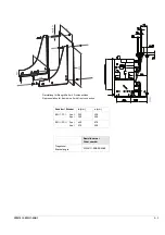
Maßbild für
Türausschnitt und Befestigungsbohrungen
Position signaling switches for guide frame
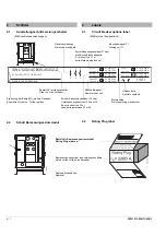
Circuit Breaker position and contact state
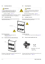
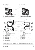
18 Mutual mechanical circuit breaker interlocking
Mutual mechanical interlocking module
Two circuit breakers against each other
Three circuit breakers among each other
Three circuit breakers among each other
(1 out of 3)
Three circuit breakers against each other
Three circuit breakers, two of them against each other 18- 8
Retrofitting interlocking module
Installing intermediate shaft and coupling
Mutual mechanical interlocking module version 1
Mutual mechanical interlocking module version 2
Fitting bowden wire on output site
Installing the bowden wire at the input of
the circuit breaker to be interlocked
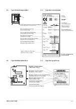
Updating the guide frame type label
Dimension drawing of door cutout
Содержание 3ZW1012-0WL11-0AB1
Страница 15: ...3ZW1012 0WL11 0AB1 0 XV ...
Страница 87: ...3ZW1012 0WL11 0AB1 8 15 S Auslösung I Auslösung S tripping I tripping ...
Страница 88: ...8 16 3ZW1012 0WL11 0AB1 Erdschlussauslösung Ground fault tripping ...
Страница 251: ...3ZW1012 0WL11 0AB1 14 15 Arranging lock assembly Installing Schlossbaugruppe vormontieren Einbau 0767 1 2 3 4 6 5 ...
Страница 359: ...3ZW1012 0WL11 0AB1 27 5 ...
Страница 360: ...27 6 3ZW1012 0WL11 0AB1 ...
Страница 366: ......
Страница 367: ......


