Circuit examples
B.2 Connection examples for fail-safe motor starters
Motor starter (3RK1308‑0**00‑0CP0)
Equipment Manual, 11/2019, A5E34821005002A/RS-AC/003
213
B.2.3
Connecting the 3DI/LC module for the motor starter
Procedure
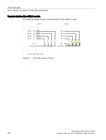
The figure below shows the connections of the 3DI/LC module:
①
Digital input 3
②
Digital input 2
③
Digital input 1
④
Local control (manual local)
⑤
Ground
⑥
24 V DC/ 100 mA output
Note
The digital inputs (1 to 4) are not isolated. The reference potential is M (5). Control the digital
inputs only via a unit supplied from the 24 V DC output (6).
Connect only cables of maximum 30 m to the 3DI/LC module.
The supply (5 and 6) is protected against short circuits.
Содержание 3RK1308-0 00-0CP0 Series
Страница 1: ...Motor starter 3RK1308 0 00 0CP0 ...
Страница 2: ......
Страница 10: ...Introduction Motor starter 3RK1308 0 00 0CP0 10 Equipment Manual 11 2019 A5E34821005002A RS AC 003 ...
Страница 16: ...Security information Motor starter 3RK1308 0 00 0CP0 16 Equipment Manual 11 2019 A5E34821005002A RS AC 003 ...
Страница 34: ...Documentation guide Motor starter 3RK1308 0 00 0CP0 34 Equipment Manual 11 2019 A5E34821005002A RS AC 003 ...
Страница 174: ...CAx data 10 1 CAx data Motor starter 3RK1308 0 00 0CP0 174 Equipment Manual 11 2019 A5E34821005002A RS AC 003 ...
Страница 204: ...Data sets A 16 I M data Motor starter 3RK1308 0 00 0CP0 204 Equipment Manual 11 2019 A5E34821005002A RS AC 003 ...
Страница 218: ...Index Motor starter 3RK1308 0 00 0CP0 218 Equipment Manual 11 2019 A5E34821005002A RS AC 003 ...


