background image

IV319 Rev.00 
Data 2010-06-22   


Pag. 46 di 118 


The UPS does not have the backup function when it is in Bypass 

mode.  The  power  used  by  the  load  is  supplied  from  the  utility 

power via internal filter.


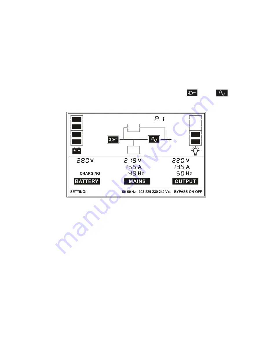
10.3 Line mode 

The LCD display in Line mode is shown in the following diagram. 

The information about the utility power, the battery, the UPS output 

and the load could be displayed. The symbol of 

³

´

 and 

³

´


indicates the UPS is working in line mode. 


Line mode


If output overloaded, the 

³

OVER LOAD

´

 is shown and the UPS will 

beep twice every second. You should get rid of some unnecessary 

loads one by one to decrease the loads connected to the UPS less 

than 90% of its nominal power capacity. 

Note:

 Please follow the following steps to connect the generator


Activate  the  generator  and  wait  until  the  operation  is  stable 

before supplying power of the generator to the UPS (be sure 

that the UPS is in idle mode). Then turn on the UPS according 

to the start-up procedure. After the UPS is turned on, then the 

loads can be connected to the UPS one by one. 


The power capacity of the AC generator should be at least twice 

Содержание Green Point 6 20KVA

Страница 1: ...IV319 Rev 00 Data 2010 06 22 Pag 1 di 118 USER MANUAL 0 18 862 e INSTALLAZIONE UPS Gruppi statici di continuit Models Green Point 6 20KVA Uninterruptible Power System...

Страница 2: ...ESCRIPTION 12 3 2 PRODUCT SPECIFICATION AND PERFORMANCE 13 4 Display Panel 16 5 Installation 20 5 1 UNPACKING AND INSPECTION 20 5 2 INPUT AND OUTPUT POWER CORDS AND PROTECTIVE EARTH GROUND INSTALLATIO...

Страница 3: ...INTERFACE 56 12 2 INTELLIGENT SLOT 56 12 3 AS400 INTERFACE OPTION 56 13 Software for all models 58 Appendix 1 The Corresponding Form of the LCD Display 59 Appendix 2 Rear Panel 60 1 Istruzioni relativ...

Страница 4: ...1 MODALIT OPERATIVA 89 6 2 FUNZIONAMENTO IN PARALLELO 91 6 3 IL TEMPO DI AUTONOMIA PER IL MODELLO STANDARD 96 7 Manutenzione della batteria 97 8 Note per lo smaltimento e la sostituzione delle batteri...

Страница 5: ...v 00 Data 2010 06 22 Pag 5 di 118 12 2 INTELLIGENT SLOT 113 12 3 INTERFACCIA AS400 OPZIONALE 114 13 Software per tutti i modelli 115 Appendice 1 Legenda del display LCD 116 Appendice 2 Pannello poster...

Страница 6: ...ng installed Please allow an acclimatization time of at least two hours Do not install the UPS near water or in damp environment Do not install the UPS where it would be exposed to direct sunlight or...

Страница 7: ...equipment it must be installed by qualified maintenance personnel Earth connection essential before connecting to the building wiring terminal 1 2 Operation Do not disconnect the earth conductor cabl...

Страница 8: ...Caution risk of electric shock The battery circuit is not isolated from the input voltage Hazardous voltages may occur between the battery terminals and the ground Verify that no voltage is present b...

Страница 9: ...1 5 Storage The UPS must be stockpiled in the room where it is ventilated and dry 1 6 Standards Safety IEC EN 62040 1 1 EMI Conducted Emission IEC EN 62040 2 Category C3 Radiated Emission IEC EN 6204...

Страница 10: ...ditional measures may be needed to prevent disturbances 2 1 Description of commonly used symbols Some or all of the following symbols may be used in this manual It is advisable to familiarize yourself...

Страница 11: ...nly used name for phase In the UPS with 3phases input the 3 phases are called Q WKLV PDQXDO WKH SKDVHV DUH QRUPDOO FDOOHG RU VRPHWLPH DUH FDOOHG 5 6 7 3KDVH A LV same as SKDVH R or 3KDVH L1 3KDVH B LV...

Страница 12: ...he utility power to direct current This direct current charges the batteries and powers the inverter On the basis of this DC voltage the inverter generates a pure sinusoidal AC voltage which is consta...

Страница 13: ...2A 65 68 65 63A 87 91 87 83A Dimension WxDxH mm 260x570x717 260x570x717 260x570x717 260x570x717 260x570x717 Weight kg 90 93 38 94 39 55 55 Note on 10K S are the version without internal battery 2 Elec...

Страница 14: ...ure 0 C 40 C 95 1000m UPS only 20 C 55 C Battery 5 C 40 C Note if the UPS is installed or used in a place where the altitude is above than 1000m the output power must be derated in use please refer to...

Страница 15: ...IV319 Rev 00 Data 2010 06 22 Pag 15 di 118 4 Basic system configuration For 6 10kVA 1 1 For 10kVA 3 1 For 15 20kVA 3 1...

Страница 16: ...ressing OFF Button and the inverter is off At this moment if Bypass is enabled then the output sockets are supplied with voltage via the bypass if the mains power is available Select Button If the UPS...

Страница 17: ...ns power Information Indicates the input voltage value Indicates the frequency value Hz of input voltage Indicates the input current value with decimal resolution Output Information Indicates the UPS...

Страница 18: ...played from 0 to 999Vdc Indicates the battery current value which could be displayed from 0 to 999A Indicates the battery capacitance percent and every grid represent 25 capacitance All the grids repr...

Страница 19: ...nings occur which need be attention UPS setting Information One of these four values of the output nominal voltage could be selected it can be modify only when the UPS is in No output or Bypass mode O...

Страница 20: ...r cords and protective earth ground installation 1 Notes for installation 1 The UPS must be installed in a location with good ventilation far away from water inflammable gas and corrosive agents 2 Ens...

Страница 21: ...dard for the UPS input and output wirings 4 For 15K 20K 3 1 UPS it is recommended to select at least 6AWG or 25mm2 wire or other insulated wire which complies with Standard for the UPS input and outpu...

Страница 22: ...er off the UPS and then disconnect the utility power supply 11 Suggest charging the batteries for 8 hours before use After connection turn the input EUHDNHU LQ WKH 21 SRVLWLRQ WKH 836 will charge the...

Страница 23: ...be connected If the UPS is used in parallel mode the Jumper between JP1 and JP2 must be removed 2 Backfeed protection If the UPS does not have an automatic protection device against current back feed...

Страница 24: ...IV319 Rev 00 Data 2010 06 22 Pag 24 di 118 technicians of the fact that the circuit is connected to a UPS install an external isolating device as shown in figure 6 10kVA For 10 20k 3 1...

Страница 25: ...dure of installing battery box should be complied with strictly Otherwise you may encounter the hazardous of electric shock 3 Where present set the battery box fuse holder LQ 2 position 4 On 6K 10K yo...

Страница 26: ...UPSs can be connected in parallel to realize output power sharing and power redundancy 2 Parallel installation 1 Users need to opt a standard 25 pin communication cable which should have 25 cores cor...

Страница 27: ...Please refer to the wiring diagram in the next page and opt suitable breaker The requirement of the output wiring is as follows When the distance between the UPSs in parallel and the breaker panel is...

Страница 28: ...IV319 Rev 00 Data 2010 06 22 Pag 28 di 118 Wiring diagram of 6K 10K 1 1 parallel system...

Страница 29: ...IV319 Rev 00 Data 2010 06 22 Pag 29 di 118 Wiring diagram of 10K 3 1 parallel system...

Страница 30: ...IV319 Rev 00 Data 2010 06 22 Pag 30 di 118 3 Operation and maintenance Wiring diagram of 15K 20K 3 1 parallel system...

Страница 31: ...p sequentially in Line mode 3 Shutdown the units shut down sequentially in INV mode When the last one completes the shutdown action each unit will shut down the inverter simultaneously and transfer to...

Страница 32: ...l beep once 3 A few seconds later the UPS turn into Line mode If the utility power is abnormal the UPS will operate in Battery mode without output interruption of the UPS 2 Turn on the UPS with no uti...

Страница 33: ...Finally not any display is shown on the display panel and no voltage is available from the UPS output Suggestions Please turn off the connected loads before turning on the UPS and turn on the loads on...

Страница 34: ...nal block Remove the maintenance cover board of each UPS and set the maintenance switch from UPS to BPS 3 Remove the cover board of the parallel port on the UPS connect each UPS one by one with the pa...

Страница 35: ...UPS 1 Before joining a new UPS user need to prepare the input and output wires the output breaker and the parallel cable 2 Turn off the input and output breakers of the new unit Connect the input wire...

Страница 36: ...Turn on each UPS in turn and observe their display Make sure that each UPS displays normal and all the UPSs transfer to the INV mode together Measure the voltage on the JP1 and JP2 on the terminal bl...

Страница 37: ...cated on the Terminal block of the UPS if the remained UPS system only remain one UPS runs by itself 5 After all panels of the UPSs do not display anything any more remove the cover board of the paral...

Страница 38: ...36 2 When turning on the UPS combine system before enter into inverter mode UPS output switch must at the OFF position 3 When UPS combine system work at inverter model please do not operate any UPS ma...

Страница 39: ...f the long backup time model is dependent on the external battery box capacity and the load level as well as other factors The backup time of standard model may vary from different models and load lev...

Страница 40: ...e regions of hot climates the battery should be charged and discharged every 2 months The standard charging time should be at least 12 hours Under normal conditions temperature between 15 C and 25 C t...

Страница 41: ...f the battery electrode otherwise it may result in electric shock or fire 6 Make sure that there is no voltage before touching the batteries The battery circuit is not isolated from the input potentia...

Страница 42: ...distributor or service center The Fault code is 05 or 06 the UPS beeps continuously The UPS transfers to fault mode due to its internal fault Please contact the distributor or service center The UPS t...

Страница 43: ...the batteries Please contact the distributor to obtain the parts and replacement service The UPS cannot power on after pressing the ON button The ON button is pressed too briefly Press the ON button...

Страница 44: ...ode Operating mode Code Warning Code Table ID Loss 21 Charger Bad 23 Fan Error 22 IP Fuse Open 24 Fault Code Table Bus Fault 05 Bypass STS Short 13 Inverter Fault 06 Battery SCR Short 14 Overload Faul...

Страница 45: ...the battery the UPS output and the load could be displayed No Output mode 10 2 Bypass mode The LCD display in Bypass mode is shown in the following diagram The information about the utility power the...

Страница 46: ...f output overloaded the OVER LOAD is shown and the UPS will beep twice every second You should get rid of some unnecessary loads one by one to decrease the loads connected to the UPS less than 90 of i...

Страница 47: ...s working in battery mode When the UPS is running in Battery mode the buzzer beeps once every 4 seconds If the ON button on the front panel is pressed for more than 1 second again the buzzer will stop...

Страница 48: ...UPS operating in parallel mode the information in code display Pn The symbol P means the UPS operating in parallel mode and the number n indicate the quantity Parallel mode 10 6 Warning mode The LCD...

Страница 49: ...following diagram The information about the utility power the battery the UPS output and the load could be displayed The symbol FAULT indicates the UPS is working in fault mode When the UPS operating...

Страница 50: ...06 22 Pag 50 di 118 Note If mode code is 10 it means that Inner Communication Fault and all the information of the UPS have not been shown except fault code information like the following diagram Com...

Страница 51: ...g 51 di 118 10 8 EPO mode In EPO mode external input EPO open the buzzer will beep once every second and the UPS pause output The output will be recovered by pressing OFF only if the EPO command is di...

Страница 52: ...for more than one second at this time the flickering black line would turn to flicker less and the output voltage rating or frequency rating or bypass state setting would be modified to the selected...

Страница 53: ...10 06 22 Pag 53 di 118 STEP 1 One flickering black line would appear underside 220 after pressing the Select button STEP 2 The flickering line would move to underside 230 after pressing the Select but...

Страница 54: ...di 118 STEP 3 The line underside 230 would turn to flicker less after pressing the Enter button and the flickering line would move to the next 240 STEP 4 The output voltage rating have been modified...

Страница 55: ...IV319 Rev 00 Data 2010 06 22 Pag 55 di 118 STEP 5 The output voltage would be 230VAC after the UPS is turned on...

Страница 56: ...r further information 12 3 AS400 Interface Option Except for the communication protocol as mentioned above this series UPS has AS400 card an optional accessory for AS400 communication protocol Please...

Страница 57: ...IV319 Rev 00 Data 2010 06 22 Pag 57 di 118 DB 9 Interface of AS400 communication protocol...

Страница 58: ...rs can monitor and control any UPS on the same LAN no matter how far from the UPSs Installation procedure 1 Go to the web site http www ups software download com winpower htm 2 Choose the operation sy...

Страница 59: ...ed in Battery mode Early warning Pn Beep twice every sec 9 BUS voltage abnormal 05 Continuously beep 10 INV abnormal 06 Continuously beep 11 Overloaded and cut off the output 07 Continuously beep 12 O...

Страница 60: ...IV319 Rev 00 Data 2010 06 22 Pag 60 di 118 Appendix 2 Rear Panel Back view of 6K Back view of 10K 1 1 and 10K 3 1...

Страница 61: ...IV319 Rev 00 Data 2010 06 22 Pag 61 di 118 Back View of 15K 20K 3 1...

Отзывы: