


3
Product description
8021386/12G4 /2019-04-24 | SICK
OPERATING INSTRUCTIONS | NAV-LOC
16
Subject to change without notice
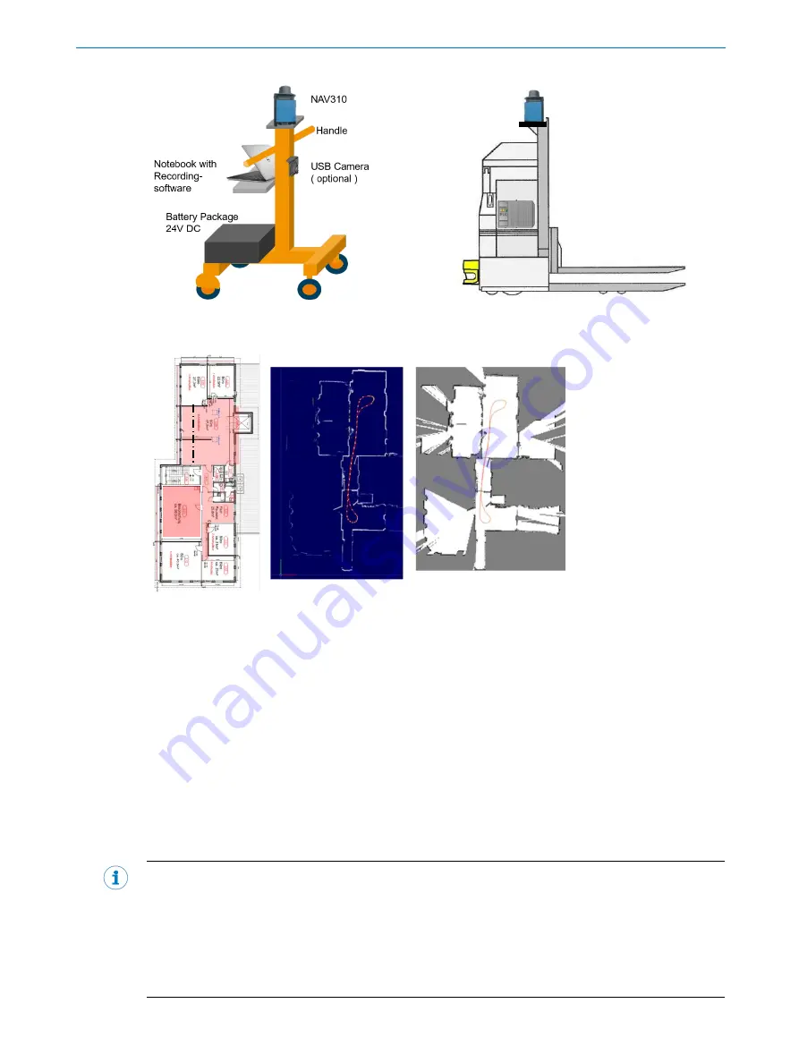
Example for measurement device
Example for AGV with NAV310
The two steps for creating a reference map are shown below.
Architecture drawing
Step 1: Raw data
Step 2: Completed reference map
(Red: measured area)
The contour visible from the sensor is dependent on the installation height of the 2D LiDAR sensor.
That is why it is necessary to observe the configuration notes in chapter 4.2 “Requirements for the
position of the 2D LiDAR sensor” when selecting the scan height and preparing the sensor for map
creation.
A coordinate system (x, y) is defined for the reference map in which the position and orientation of the
sensor is determined numerically during localization. The orientation and the origin point of this coor-
dinate system can only be configured when creating the map and must therefore be defined for the
respective plant before creating the reference map.
The reference map must be loaded on the SIM to operate NAV-LOC. This step is described in chapter
7.5.
The map used must cover the entire vehicle operation area.
If needed, for example when operating on different levels connected by an elevator, different reference
maps can be used. However, only one map can be active at a time.
NOTE
If modifications are made in the factory site which result in a considerable change to the contour visible
from the sensor, for example due to modified walls, racks or other large structures, the accuracy of the
localization in the affected area is reduced or the localization itself is impaired. In this case, the affected
area must be re-mapped. Contact SICK Service about this.
The reference map is in the *.smap data format. You will receive a graphic representation of the refer-
ence map documentation. An imprinted grid enables orientation.


