Chapter
10
Operating Instructions
CLV 490 Bar Code Scanner
10-44
©
SICK AG · Division Auto Ident · Germany · All rights reserved
8 008 796/0000/25-06-2002
Appendix
1.
Connect the PC to the terminal interface on the CLV using a RS 232 cable (AMV/S 60:
connect the PC to the internal 9-pin "Service" plug).
See
Chapter 5.5.5 Connecting the CAN interface, Page 5-15
.
2.
Click
(AutoBaud detect) in the toolbar or choose O
PTIONS
, A
UTO
B
AUD
D
ETECT
.
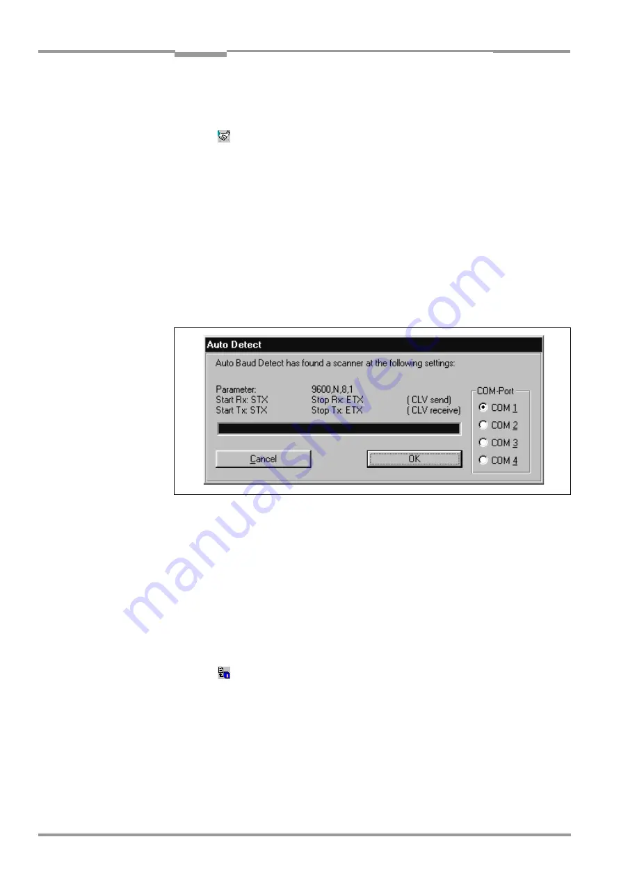
CLV-Setup scans the serial interface by varying the communication parameters and
sends a telegram to the CLV repeatedly. As soon as a response is registered from the
CLV, CLV-Setup signals the detected communication parameters.
shows an
example of the results of the AutoBaud detect function. The C
ONNECTED
status is dis-
played right in the status bar in the bottom of the screen.
3.
Confirm the A
UTO
D
ETECT
dialog box with OK.
CLV-Setup displays the detected CLV type in a separate dialog box and asks you
whether you want to upload the current parameter set from the CLV.
4.
Confirm the dialog box with Yes.
CLV-Setup uploads the current parameter set from the RAM of the CLV to its database
and displays the values on the tabs.
You can edit the current parameter set on the tabs.
– or–
2.
Choose O
PTIONS
, S
ERIAL
I
NTERFACE
from the menu bar.
CLV-Setup displays the current communication parameter settings on the PC in the
COM P
ARAMETERS
dialog box.
3.
Make sure that the communication parameters on the PC and CLV are identical
(
connected
COM port, 9 600 bit/s, 8 data bits, 1 stop bit, no parity
)
4.
Confirm the dialog box with OK.
CLV-Setup attempts to communicate with the CLV again.
If it is successful, it displays the C
ONNECTED
status right in the status bar in the bottom
of the screen.
5.
Click
in the toolbar.
CLV-Setup then uploads the current parameter set from the RAM of the CLV to its
database and displays the values on the tabs.
You can edit the current parameter set on the tabs.
Fig. 10-36: CLV-Setup: Result display of the AutoBaud Detect function