


10
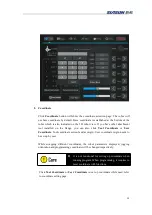
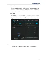
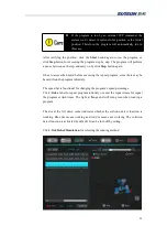
System will show the robot installation orientation and flange loading information. For
example, “Robot install: Longitudinal TCP load 0 kg”. If any information does NOT
match with actual, for safety concern, please modify them from system setting before
any other operations. These parameter settings will affect the zero-gravity manual
jogging function and the collision detection function. Click “Modify” button for further
editing.
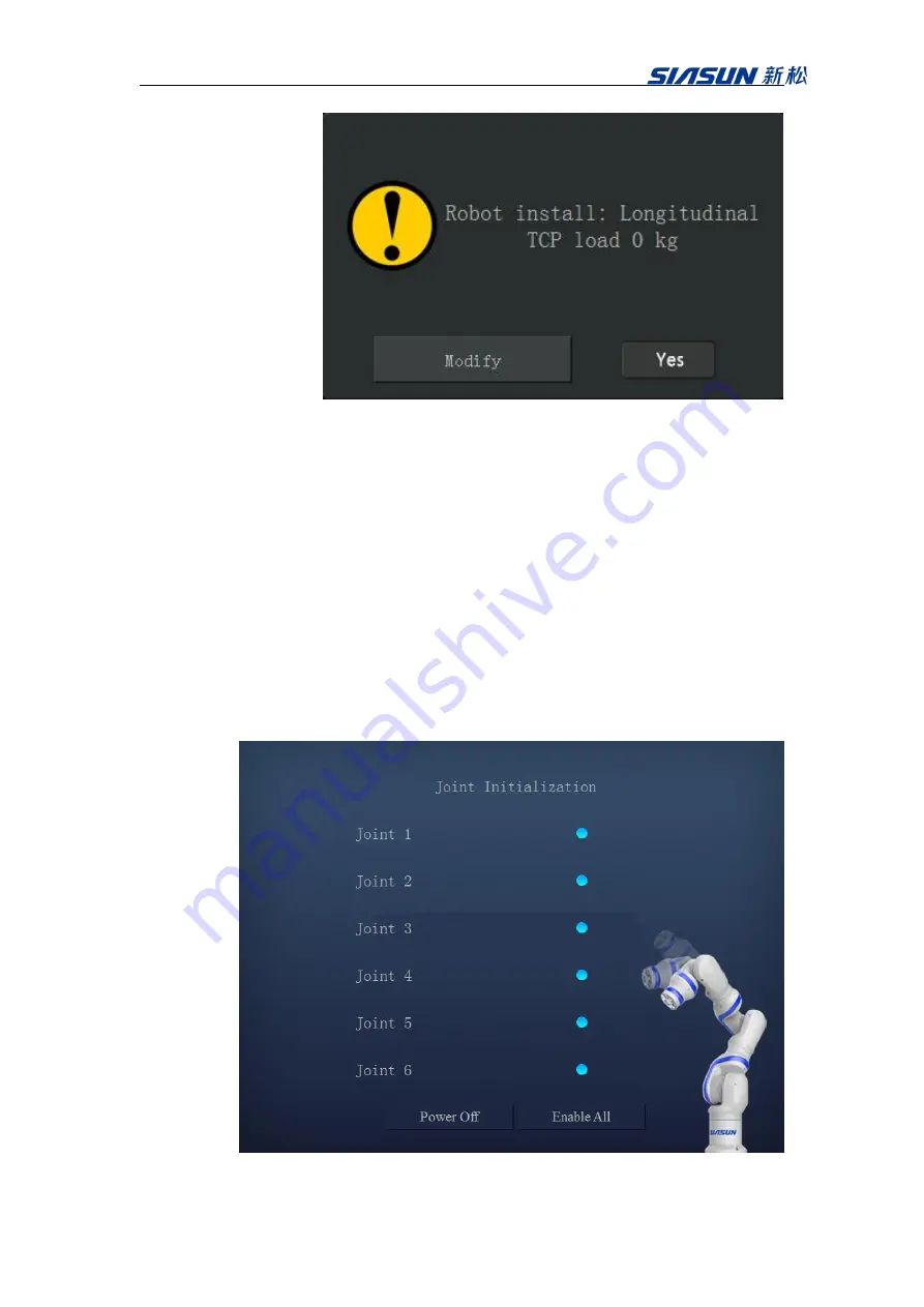
Click “OK” button, while the above information has been verified. The white flange
light demonstrates the robot has been power on. The first time power on process may
take a while for initializing. After each axis has been initialized, the stand-by indicators
turn from red to blue on demonstrator. Click “Enable All” button to enable the control of
the robot and release all axial breaks. After the flange light turns blue, which indicates
all axial breaks have been released, the robot is ready to be operated via demonstrator.
Содержание GCR Series
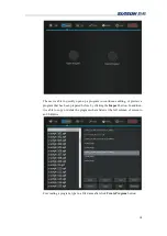
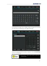
Страница 41: ...37 6 Robot Programming 6 1 Create program Click Create Program and enter a program name ...
Страница 47: ...43 The functions illustrate below are functions for IO The function illustrate below are logic function ...
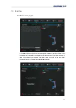
Страница 51: ...47 6 6 Example Add a movej and movel node respectively Then add a MoveC node and set it s sub nodes position ...
Страница 53: ...49 ...
Страница 86: ...82 signal_name It represents the name of the modbus node Return Value none Example modbus_delete_signal mbus1 ...


