19
19
OPERATION CMT-240-K
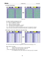
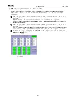
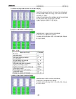
(4) All alarm status display
[Fig. 5.2-6]
The status of all alarms is displayed [Fig. 5.2-6].
The contents of the display is as shown below.
A1 : Alarm 1 is indicated by a red light.
A2 : Alarm 2 is indicated by a red light.
HB : Heater burnout alarm is indicated by a red light.
LP : Loop break alarm is indicated by a red light.
UP : If the sensor input exceeds the rated scale high limit value, it is indicated by a red light.
DOW : If the sensor input exceeds the rated scale low limit value, it is indicated by a red light.
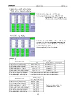
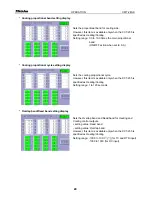
(5) MV, Heater current value and PID auto-tuning status display
[Fig. 5.2-7]
MV, heater current value and PID auto-tuning status are indicated on the display [Fig. 5.2-7].
Display details are as follows.
AT
: While PID auto-tuning is performing, a yellow light blinks.
MV
: Indicates control output manipulated variable (%).
Heater current: Indicates heater current (ampere) value.
0.0 is indicated even if the option Heater burnout alarm [code: W] is not applied.

