16
16
OPERATION CMT-240-K
5. Operation
5.1 Display configuration
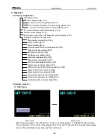
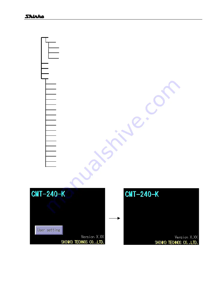
Title display (P.16)
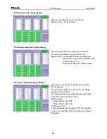
User setting display (P.17)
Channel name change display (P.17)
The number of blocks of C series setting display (P.17)
DC input decimal point place change display (P.17)
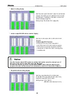
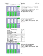
PV, SV and Control output status display (P.18)
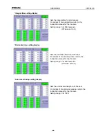
All alarm status display (P.19)
MV, Heater current value, PID auto-tuning status display (P.19)
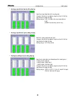
Setting item selection display (P.20)
Main setting value setting (P.24)
Alarm 1 setting (P.24)
Alarm 2 setting (P.25)
Control output ON/OFF status selection (P.25)
Proportional band setting (P.25)
Integral time setting (P.26)
Derivative time setting (P.26)
Anti-reset windup setting (P.26)
Proportional cycle setting (P.27)
PD action manual reset setting (P.27)
Heater burnout alarm setting (P.27)
PID Auto-tuning Perform/Cancel selection (P.28)
Alarm 1 action form selection (P.28)
Alarm 2 action form selection (P.28)
Cooling proportional band setting (P.29)
Cooling proportional cycle setting (P.29)
Overlap band/dead band setting (P.29)
5.2 Display operation
(1) Title display
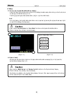
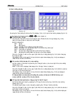
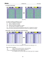
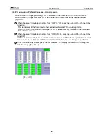
[Fig. 5.2-1]
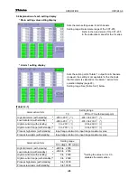
[Fig. 5.2-2]
After the power supply to the CMT-240-K is turned on, the Title display 1 is indicated for approximately
10 seconds [Fig. 5.2-1], and then Title display 2 [Fig. 5.2-2] and PV, SV and Control output status display
[Fig. 5.2-5] are indicated respectively, and the control starts.

