


53(83)
:
If main arm in grasp on state, press this key will grasp off
.
If main arm in grasp off state, press this key will grasp on
.
:
If sub-arm in up state, press this key will move down
.
If sub-arm in down state, press this key will move up .
:
If sub-arm in forward state, press this key will move backward
.
If sub-arm in backward state, press this key will move forward
.
:
If sub-arm in grip on state, press this key will grip off
.
If sub-arm in grip off state, press this key will grip on.
Press
to confirm arm actions and edit delay time.
Press
to confirm arm actions record, cursor moves to next record.
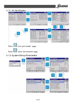
Loop actions:
Press
into Select Loop Area page.
Insert loop area page:
Press
to select sub-programs.
Press
to insert selected loop.
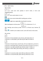
Insert extend IO:
In
“
teach mode
”
page, press
to edit extend IO port.
In
“
Extend IO Port Editor
”
page, press
to select options.
: clear IO port when selecting port.
Содержание ST2
Страница 2: ......
Страница 8: ...8 83 ...
Страница 31: ...31 83 4 Operating Instruction 4 1 Hand Controller 4 1 1 Operation Panel of Hand Controller ...
Страница 63: ...63 83 7 Assembly Diagram 7 1 Traverse Unit Picture 7 1 Traverse Unit ...
Страница 65: ...65 83 7 3 Main Arm Unit Picture 7 2 Main Arm Unit ...
Страница 67: ...67 83 7 5 Crosswise Unit Picture 7 3 Crosswise Unit ...
Страница 69: ...69 83 8 Electric Control Chart 8 1 The Power Input Wiring Diagram Picture 8 1 The Power Input Wiring Diagram ...
Страница 70: ...70 83 8 2 The Panasonic Servo Motor Wiring Diagram Picture 8 2 The Panasonic Servo Motor Wiring Diagram ...
Страница 76: ...76 83 8 8 Z axis I O Board Wiring Diagram Picture 8 8 Z axis I O Board Wiring Diagram ...
Страница 77: ...77 83 8 9 Main Arm Wiring Diagram 1 Picture 8 9 Main Arm Wiring Diagram 1 ...
Страница 78: ...78 83 8 10 Main Arm Wiring Diagram 2 Picture 8 10 Main Arm Wiring Diagram 2 ...
Страница 79: ...79 83 8 11 Sub arm Wiring Diagram Picture 8 11 Sub arm Wiring Diagram ...
Страница 82: ...82 83 8 14 Main Control Board Component Layout U1 Picture 8 14 Main Control Board Component Layout U1 ...
Страница 83: ...83 83 8 15 Pneumatic Schematic Diagram Picture 8 15 Pneumatic Schematic Diagram ...


