


42(83)
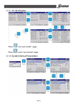
4.9 Modify Program Parameters
Use
to choose options.
Press
to choose servo mode when modify position parameter.
Press
, servo Y down/ servo X forward.
Press
, servo Y up/ servo X backward.
Press
, servo Z traverse in.
Press
, servo Z traverse out.
Press
, increase servo speed when modify position parameter; insert
value when modify delay time.
Press
, decrease servo speed when modify position parameter; reduce
value when modify delay time.
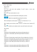
used as number
when modify delay time parameter.
Press
to move cursor when modify delay time parameter.
Press
to save parameter and screen back to last page.
Press
to give up modified parameter and screen back to last page.
Note: in auto running mode, servo position just can be adjusted 0.1mm or
1.0mm unit, each modify can not over
±
5mm.
4.10 Modify Production Schedule
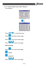
Press
to select options.
Press
to increase value.
Содержание ST2
Страница 2: ......
Страница 8: ...8 83 ...
Страница 31: ...31 83 4 Operating Instruction 4 1 Hand Controller 4 1 1 Operation Panel of Hand Controller ...
Страница 63: ...63 83 7 Assembly Diagram 7 1 Traverse Unit Picture 7 1 Traverse Unit ...
Страница 65: ...65 83 7 3 Main Arm Unit Picture 7 2 Main Arm Unit ...
Страница 67: ...67 83 7 5 Crosswise Unit Picture 7 3 Crosswise Unit ...
Страница 69: ...69 83 8 Electric Control Chart 8 1 The Power Input Wiring Diagram Picture 8 1 The Power Input Wiring Diagram ...
Страница 70: ...70 83 8 2 The Panasonic Servo Motor Wiring Diagram Picture 8 2 The Panasonic Servo Motor Wiring Diagram ...
Страница 76: ...76 83 8 8 Z axis I O Board Wiring Diagram Picture 8 8 Z axis I O Board Wiring Diagram ...
Страница 77: ...77 83 8 9 Main Arm Wiring Diagram 1 Picture 8 9 Main Arm Wiring Diagram 1 ...
Страница 78: ...78 83 8 10 Main Arm Wiring Diagram 2 Picture 8 10 Main Arm Wiring Diagram 2 ...
Страница 79: ...79 83 8 11 Sub arm Wiring Diagram Picture 8 11 Sub arm Wiring Diagram ...
Страница 82: ...82 83 8 14 Main Control Board Component Layout U1 Picture 8 14 Main Control Board Component Layout U1 ...
Страница 83: ...83 83 8 15 Pneumatic Schematic Diagram Picture 8 15 Pneumatic Schematic Diagram ...


