


43(83)
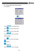
Press
to reduce value.
Press
to move cursor when modify parameters.
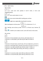
used as number
when input value.
Press
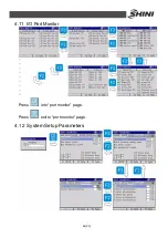
to save parameter and back to branch program page.
Press
to give up modifying parameter.
Count Setup (system parameter):
Production Schedule: Set the production schedule, when the released product
number reaches this count, system will suspend and inform that the production
schedule has finished. The minimum is 0, means no production schedule. The
maximum of production schedule is 9999999.
Reject sum for alarm: Set the reject sum for alarm. When the reject number
reaches this count, system will suspend and inform that the reject is out of
standard. The minimum is 0, means no reject alarm. The maximum is 9999.
P.Arm (main arm) Vacuum Check: setup
“
main arm vacuum check
”
to use or
unused.
P.Arm (main arm) Grasp Check: setup
“
main arm grasp check
”
to use or
unused.
P.Arm (main arm) Grip Check: setup
“
main arm grip check
”
to use or unused.
Содержание ST2
Страница 2: ......
Страница 8: ...8 83 ...
Страница 31: ...31 83 4 Operating Instruction 4 1 Hand Controller 4 1 1 Operation Panel of Hand Controller ...
Страница 63: ...63 83 7 Assembly Diagram 7 1 Traverse Unit Picture 7 1 Traverse Unit ...
Страница 65: ...65 83 7 3 Main Arm Unit Picture 7 2 Main Arm Unit ...
Страница 67: ...67 83 7 5 Crosswise Unit Picture 7 3 Crosswise Unit ...
Страница 69: ...69 83 8 Electric Control Chart 8 1 The Power Input Wiring Diagram Picture 8 1 The Power Input Wiring Diagram ...
Страница 70: ...70 83 8 2 The Panasonic Servo Motor Wiring Diagram Picture 8 2 The Panasonic Servo Motor Wiring Diagram ...
Страница 76: ...76 83 8 8 Z axis I O Board Wiring Diagram Picture 8 8 Z axis I O Board Wiring Diagram ...
Страница 77: ...77 83 8 9 Main Arm Wiring Diagram 1 Picture 8 9 Main Arm Wiring Diagram 1 ...
Страница 78: ...78 83 8 10 Main Arm Wiring Diagram 2 Picture 8 10 Main Arm Wiring Diagram 2 ...
Страница 79: ...79 83 8 11 Sub arm Wiring Diagram Picture 8 11 Sub arm Wiring Diagram ...
Страница 82: ...82 83 8 14 Main Control Board Component Layout U1 Picture 8 14 Main Control Board Component Layout U1 ...
Страница 83: ...83 83 8 15 Pneumatic Schematic Diagram Picture 8 15 Pneumatic Schematic Diagram ...


