


14(83)
The power requirements are given on the type plate if the robot, the power
connection is provided through a normal power cord and a CEE plug.
The power connection should be performed only by authorized
electrician and should be in accordance with any applicable regulations.
2.1.4
Safety Fence
1. After installing the robot, indicate the safety fence outside the scope of the
robot working area.
2. The hand controller should be fixed outside of the safety fence.
3. Stick the warning signals on outstanding place of the fence.
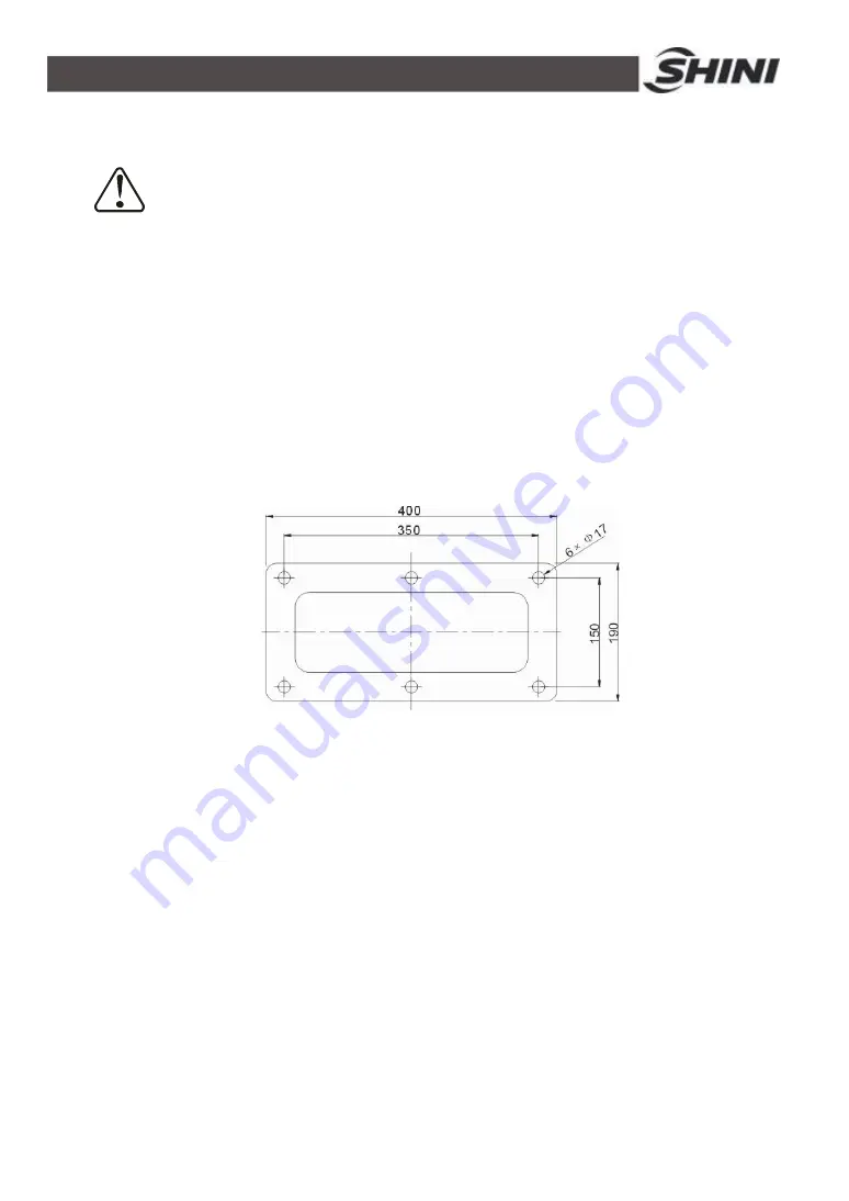
2.1.5
Mounting Preparation
1. Before drilling, switch off the injection molding machine and then turn off the
power, avoid the scrap-iron into the mold.
2. Stock the drilling picture on the installing surface of IMM.
3. Use the center punch to assist drilling.
4. Place the magnetic drill on the fixing plate, use drill bits (
Ф
14) to drill holes
about 30mm depth.
5. Tapping. Use M16 tap to produce internal 6 screws threads about 25mm
depth.
2.1.6
Mounting Instruction
1. Should avoid vibration, collision and falling, when transfer the top of IMM.
2. Alignment holes, using the 8mm torque wrench turn to 77Nm tightens the
M16
×
30 hex socket screws.
Содержание ST2
Страница 2: ......
Страница 8: ...8 83 ...
Страница 31: ...31 83 4 Operating Instruction 4 1 Hand Controller 4 1 1 Operation Panel of Hand Controller ...
Страница 63: ...63 83 7 Assembly Diagram 7 1 Traverse Unit Picture 7 1 Traverse Unit ...
Страница 65: ...65 83 7 3 Main Arm Unit Picture 7 2 Main Arm Unit ...
Страница 67: ...67 83 7 5 Crosswise Unit Picture 7 3 Crosswise Unit ...
Страница 69: ...69 83 8 Electric Control Chart 8 1 The Power Input Wiring Diagram Picture 8 1 The Power Input Wiring Diagram ...
Страница 70: ...70 83 8 2 The Panasonic Servo Motor Wiring Diagram Picture 8 2 The Panasonic Servo Motor Wiring Diagram ...
Страница 76: ...76 83 8 8 Z axis I O Board Wiring Diagram Picture 8 8 Z axis I O Board Wiring Diagram ...
Страница 77: ...77 83 8 9 Main Arm Wiring Diagram 1 Picture 8 9 Main Arm Wiring Diagram 1 ...
Страница 78: ...78 83 8 10 Main Arm Wiring Diagram 2 Picture 8 10 Main Arm Wiring Diagram 2 ...
Страница 79: ...79 83 8 11 Sub arm Wiring Diagram Picture 8 11 Sub arm Wiring Diagram ...
Страница 82: ...82 83 8 14 Main Control Board Component Layout U1 Picture 8 14 Main Control Board Component Layout U1 ...
Страница 83: ...83 83 8 15 Pneumatic Schematic Diagram Picture 8 15 Pneumatic Schematic Diagram ...


