


56(83)
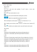
Insert IMM action:
In teach program page,
Press
into IMM signal page.
In IMM signal page, press
to select signal.
Press
to confirm IMM actions and return to program page, insert IMM
actions .
Press
give up selection and return to teach program page.
Insert others action:
In teach program page,
press
into the others action page.
In the others action page, press
to
select other actions.
Press
to confirm selection and back to teach program page, insert
combine action /branch checking/combine end .
Press
to give up selection and back to teach program page.
4.16.3 Program Branch Control
Conditional control:
Format of conditional control is as below:
IF [condition]
{
serial action A
}
ELSE
{
serial action B
}
ENDIF
Program will judge the condition firstly, if equals the condition, then execute
serial action A. Otherwise, execute serial action B.
The conditional control can also have no ELSE, as below:
Содержание ST2
Страница 2: ......
Страница 8: ...8 83 ...
Страница 31: ...31 83 4 Operating Instruction 4 1 Hand Controller 4 1 1 Operation Panel of Hand Controller ...
Страница 63: ...63 83 7 Assembly Diagram 7 1 Traverse Unit Picture 7 1 Traverse Unit ...
Страница 65: ...65 83 7 3 Main Arm Unit Picture 7 2 Main Arm Unit ...
Страница 67: ...67 83 7 5 Crosswise Unit Picture 7 3 Crosswise Unit ...
Страница 69: ...69 83 8 Electric Control Chart 8 1 The Power Input Wiring Diagram Picture 8 1 The Power Input Wiring Diagram ...
Страница 70: ...70 83 8 2 The Panasonic Servo Motor Wiring Diagram Picture 8 2 The Panasonic Servo Motor Wiring Diagram ...
Страница 76: ...76 83 8 8 Z axis I O Board Wiring Diagram Picture 8 8 Z axis I O Board Wiring Diagram ...
Страница 77: ...77 83 8 9 Main Arm Wiring Diagram 1 Picture 8 9 Main Arm Wiring Diagram 1 ...
Страница 78: ...78 83 8 10 Main Arm Wiring Diagram 2 Picture 8 10 Main Arm Wiring Diagram 2 ...
Страница 79: ...79 83 8 11 Sub arm Wiring Diagram Picture 8 11 Sub arm Wiring Diagram ...
Страница 82: ...82 83 8 14 Main Control Board Component Layout U1 Picture 8 14 Main Control Board Component Layout U1 ...
Страница 83: ...83 83 8 15 Pneumatic Schematic Diagram Picture 8 15 Pneumatic Schematic Diagram ...


