


34(83)
I/O extend distribute:
System with 4 extra input ports and 5 extra output ports:
input extend port
output extend port
position
No.
quantity
No.
quantity
main control
board
XET00
~
XET03
4
YET00
~
YET04
5
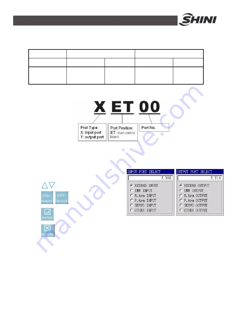
I/O extend cording
I/O extends operation:
The following page will display on screen when system needs to choose
input/output port.
Press
to choose port position.
Press
to choose port No.
Press
to choose option port and return to last page.
Press
to give up option port and back to last page.
4.3 Loop
System with 10 loop areas, each cycle loop has different area according to
different cycle time. Each cycle loop has two place modes: any 10 positions and
matrix.
Any 10 positions mode:
Min: 1 position, max: 10 positions.
Z-axis and Y-axis servo: each positions defined by Z-axis and Y-axis. One cycle
Содержание ST2
Страница 2: ......
Страница 8: ...8 83 ...
Страница 31: ...31 83 4 Operating Instruction 4 1 Hand Controller 4 1 1 Operation Panel of Hand Controller ...
Страница 63: ...63 83 7 Assembly Diagram 7 1 Traverse Unit Picture 7 1 Traverse Unit ...
Страница 65: ...65 83 7 3 Main Arm Unit Picture 7 2 Main Arm Unit ...
Страница 67: ...67 83 7 5 Crosswise Unit Picture 7 3 Crosswise Unit ...
Страница 69: ...69 83 8 Electric Control Chart 8 1 The Power Input Wiring Diagram Picture 8 1 The Power Input Wiring Diagram ...
Страница 70: ...70 83 8 2 The Panasonic Servo Motor Wiring Diagram Picture 8 2 The Panasonic Servo Motor Wiring Diagram ...
Страница 76: ...76 83 8 8 Z axis I O Board Wiring Diagram Picture 8 8 Z axis I O Board Wiring Diagram ...
Страница 77: ...77 83 8 9 Main Arm Wiring Diagram 1 Picture 8 9 Main Arm Wiring Diagram 1 ...
Страница 78: ...78 83 8 10 Main Arm Wiring Diagram 2 Picture 8 10 Main Arm Wiring Diagram 2 ...
Страница 79: ...79 83 8 11 Sub arm Wiring Diagram Picture 8 11 Sub arm Wiring Diagram ...
Страница 82: ...82 83 8 14 Main Control Board Component Layout U1 Picture 8 14 Main Control Board Component Layout U1 ...
Страница 83: ...83 83 8 15 Pneumatic Schematic Diagram Picture 8 15 Pneumatic Schematic Diagram ...


