


97(142)
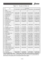
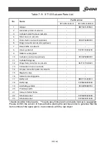
Table 7- 2
:
Travese Unit Parts List
Part Number
No.
Name
ST1-850-1400-S
ST1-850-1600D-S
1
Base
-
-
2
End cover of beam
-
-
3
In mold home position plate
BL71001410020
BL71001410020
4
Limited sensor panel
BL69335000020
BL69335000020
5
Linear guiding rail
-
-
6
Belt fixing frame
BL71010900020
BL71010900020
7
Buffer unit
BH91151200010
BH91151200010
8
Buffer cap
YW80200000000
YW80200000000
9
Belt holding plate
YW09474000110
YW09474000110
10
Belt splint connectiong piece
BL70110100020
BL70110100020
11
Synchronous belt
YR00082500100
YR00082500100
12
Proximity switch
-
-
13
Servo motor
-
-
14
Speed reducer
YM50940000000
YM50940000000
15
Traverse drag chain connecter
BL71555300020
BL71555300020
16
Package supporting frame1
BL71555600020
BL71555600020
17
Flip fixing plate
BH10555800010
BH10555800010
18
Package supporting frame2
BL71555700020
BL71555700020
19
Washer
BH79051100110
BH79051100110
20
Sliding seat
-
-
21
Motor supporting frame
BH10155000010
BH10155000010
23
Pulley bearing
YW11600500000
YW11600500000
24
Pulley
BH91030000010
BH91030000010
22
Connection shaft
BH91303900010
BH91303900010
25
Special washer
BL70107700040
BL70107700040
26
Synchronous pulley
YW08621900100
YW08621900100
27
Motor sypporting cover
BL21000100520
BL21000100520
28
Hinge
YW06253200000
YW06253200000
29
Lock
BL70112100020
BL70112100020
30
Trapezoid plastic handle
YR40914040000
YR40914040000
31
Sliding seat cover
BL70127000020
BL70127000020
32
Travese drag chain
YE60250007500
YE60250007500
33
Buffer mount plate 3
-
-
34
Safety sensor panel of mold
BL69002200020
BL69002200020
35
Aluminum profile of traverse
-
-
36
Traverse drag chain supporting frame
-
-
37
Control box
BBH72070000250
BH72070000250
38
Filter regulating valve
YE30320400100
YE30320400100
*means possible broken parts. **means easy broken part, and spare backup is suggested.
Please confirm the version of manual before placing the purchase order to gurantee that the
item number of the spare part is in accordance with the real object.
Содержание ST1-S
Страница 1: ...ST1 S User Manual Date May 2016 Vision V1 0 English ...
Страница 2: ......
Страница 10: ...10 142 ...
Страница 41: ...41 142 4 Operating Instruction 4 1 Hand Controller 4 1 1Operation Pannel of Hand Controller Picture 4 1 ...
Страница 94: ...94 142 7 Assembly Diagram 7 1 Traverse Unit ST1 S and ST1 T S Picture 7 1 ...
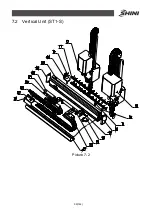
Страница 99: ...99 142 7 2 Vertical Unit ST1 S Picture 7 2 ...
Страница 102: ...102 142 7 3 Main Arm Unit ST1 S Picture 7 3 ...
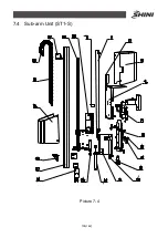
Страница 105: ...105 142 7 4 Sub arm Unit ST1 S Picture 7 4 ...
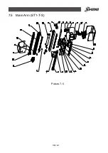
Страница 108: ...108 142 7 5 Main Arm ST1 T S Picture 7 5 ...
Страница 110: ...110 142 7 6 Sub arm ST1 T S Picture 7 6 ...
Страница 113: ...113 142 7 7 Vertical ST1 T S Picture 7 7 ...
Страница 115: ...115 142 7 8 Traverse Unit ST1 T S Middle Telescopic Arm Picture 7 8 ...
Страница 119: ...119 142 7 9 Main Arm ST1 T S Middel Telescopic Arm Picture 7 9 ...
Страница 123: ...123 142 7 10 Sub arm ST1 T S Middel Telescopic Arm Picture 7 10 ...
Страница 127: ...127 142 7 11 Crosswise Unit ST1 T S Middle Telescopic Arm Picture 7 11 ...
Страница 131: ...131 142 8 1 2 The Panasonic Servo Motor and Servo Driver Wiring Diagram Picture 8 2 ...
Страница 132: ...132 142 8 1 3 The Panasonic Servo Motor and I O Board Wiring Diagram Picture 8 3 ...
Страница 133: ...133 142 8 1 4 The Delta Servo Motor and Servo Driver Wiring Diagram Picture 8 4 ...
Страница 134: ...134 142 8 1 5 The Delta Servo Motor and I O Board Wiring Diagram Picture 8 5 ...
Страница 135: ...135 142 8 1 6 The Cuinsico Servo Motor and Servo Driver Wiring Diagram Picture 8 6 ...
Страница 136: ...136 142 8 1 7 The Cuinsico Servo Motor and I O Board Wiring Diagram Picture 8 7 ...
Страница 137: ...137 142 8 1 8 Z axis I O Board Wiring Diagram Picture 8 8 ...
Страница 138: ...138 142 8 1 9 Main Arm Wiring Diagram Picture 8 9 ...
Страница 139: ...139 142 8 1 10 Sub arm Wiring Diagram Picture 8 10 ...
Страница 140: ...140 142 8 1 11 Main Arm Output Wirng Diagram Picture 8 11 ...
Страница 141: ...141 142 8 1 12 Signals Input Wiring Diagram Picture 8 12 ...
Страница 142: ...142 142 8 1 13 Signals Output Wiring Diagram Picture 8 13 ...


