40(142)
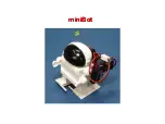
Picture 3-7
:
before modified
Picrue 3-8
:
after modified
6. Horizontal rotate robot base 180 degree and move to the other end of beam
then tighten it.
7. Robot reversing result checking. Press
“
home position
”
, robot will move
reverse. After robot back to home position, Z-axis home position
sensor(X103) light up. When robot running, limit sensor light up.
Содержание ST1-S
Страница 1: ...ST1 S User Manual Date May 2016 Vision V1 0 English ...
Страница 2: ......
Страница 10: ...10 142 ...
Страница 41: ...41 142 4 Operating Instruction 4 1 Hand Controller 4 1 1Operation Pannel of Hand Controller Picture 4 1 ...
Страница 94: ...94 142 7 Assembly Diagram 7 1 Traverse Unit ST1 S and ST1 T S Picture 7 1 ...
Страница 99: ...99 142 7 2 Vertical Unit ST1 S Picture 7 2 ...
Страница 102: ...102 142 7 3 Main Arm Unit ST1 S Picture 7 3 ...
Страница 105: ...105 142 7 4 Sub arm Unit ST1 S Picture 7 4 ...
Страница 108: ...108 142 7 5 Main Arm ST1 T S Picture 7 5 ...
Страница 110: ...110 142 7 6 Sub arm ST1 T S Picture 7 6 ...
Страница 113: ...113 142 7 7 Vertical ST1 T S Picture 7 7 ...
Страница 115: ...115 142 7 8 Traverse Unit ST1 T S Middle Telescopic Arm Picture 7 8 ...
Страница 119: ...119 142 7 9 Main Arm ST1 T S Middel Telescopic Arm Picture 7 9 ...
Страница 123: ...123 142 7 10 Sub arm ST1 T S Middel Telescopic Arm Picture 7 10 ...
Страница 127: ...127 142 7 11 Crosswise Unit ST1 T S Middle Telescopic Arm Picture 7 11 ...
Страница 131: ...131 142 8 1 2 The Panasonic Servo Motor and Servo Driver Wiring Diagram Picture 8 2 ...
Страница 132: ...132 142 8 1 3 The Panasonic Servo Motor and I O Board Wiring Diagram Picture 8 3 ...
Страница 133: ...133 142 8 1 4 The Delta Servo Motor and Servo Driver Wiring Diagram Picture 8 4 ...
Страница 134: ...134 142 8 1 5 The Delta Servo Motor and I O Board Wiring Diagram Picture 8 5 ...
Страница 135: ...135 142 8 1 6 The Cuinsico Servo Motor and Servo Driver Wiring Diagram Picture 8 6 ...
Страница 136: ...136 142 8 1 7 The Cuinsico Servo Motor and I O Board Wiring Diagram Picture 8 7 ...
Страница 137: ...137 142 8 1 8 Z axis I O Board Wiring Diagram Picture 8 8 ...
Страница 138: ...138 142 8 1 9 Main Arm Wiring Diagram Picture 8 9 ...
Страница 139: ...139 142 8 1 10 Sub arm Wiring Diagram Picture 8 10 ...
Страница 140: ...140 142 8 1 11 Main Arm Output Wirng Diagram Picture 8 11 ...
Страница 141: ...141 142 8 1 12 Signals Input Wiring Diagram Picture 8 12 ...
Страница 142: ...142 142 8 1 13 Signals Output Wiring Diagram Picture 8 13 ...