


128(142)
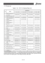
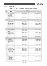
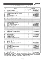
7.11.1
Parts List
Table 7- 19
:
ST1-T-S (Middle Telescopic Arm) Crosswise Unit
Part Number
No.
Name
ST1-1100-1800T
ST1-1100-1800DT
ST1-1300-2000T
ST1-1300-2000T
1
Crosswise beam
base
-
-
-
-
2
Buffer fixing block 6
BH78511300040
BH78511300040
BH78511300040
BH78511300040
3
Buffer fixing block 5
BH78511200040
BH78511200040
BH78511200040
BH78511200040
4
Cylinder holder
frame on sub-arm
-
-
-
-
5
Crosswise cylinder
rod clamping device
BH78110000040
BH78110000040
BH78110000040
BH78110000040
6
Crosswise cylinder
fixing frame on
sub-arm
-
BL72104000040
-
BL72104000040
7
Linear guide rail
-
YW31002011000
-
8
Shock absorber
-
-
-
-
9
Crosswise cylinder
on sub-arm
-
BL72100800040
-
BL72100800040
10
Crosswise cylinder
holder on main arm
-
-
-
-
11
Sensor fixing sheet
YW09601400110
YW09601400110
YW09601400110
YW09601400110
12
Crosswise cylinder
fixing frame of mian
arm
BL72101100040
BL72101100040
BL72101100040
BL72101100040
13
Crosswise cylinder
on main arm
YE31140108400
YE31140108400
YE31140108400
YE31140108400
14
Main arm
BH78111800010
BH78111800010
BH78111800010
BH78111800010
15
Sub-arm
-
BH78180021010
-
BH78180021010
16
Right cover of
crosswise beam
BH91905000010
BH91905000010
BH91905000010
BH91905000010
17
Limit baffer 3
-
-
-
-
18
Buffer installation
part
-
-
-
-
19
Buffer cap
-
-
-
-
20
Crosswise drag
mounting plate
-
-
-
-
21
Crosswise drag
supporting frame
-
-
-
-
22
Crosswise drag on
main arm
YE60250003100
YE60250003100
YE60250003100
YE60250003100
23
Crosswise drag on
sub-arm
-
YE60250005500
-
YE60250005500
24
Cover of crosswise
BL72101800020
BL72101800020
BL72101800020
BL72101800020
*means possible broken parts. **means easy broken part, and spare backup is suggested.
Please confirm the version of manual before placing the purchase order to gurantee that the
item number of the spare part is in accordance with the real object.
Содержание ST1-S
Страница 1: ...ST1 S User Manual Date May 2016 Vision V1 0 English ...
Страница 2: ......
Страница 10: ...10 142 ...
Страница 41: ...41 142 4 Operating Instruction 4 1 Hand Controller 4 1 1Operation Pannel of Hand Controller Picture 4 1 ...
Страница 94: ...94 142 7 Assembly Diagram 7 1 Traverse Unit ST1 S and ST1 T S Picture 7 1 ...
Страница 99: ...99 142 7 2 Vertical Unit ST1 S Picture 7 2 ...
Страница 102: ...102 142 7 3 Main Arm Unit ST1 S Picture 7 3 ...
Страница 105: ...105 142 7 4 Sub arm Unit ST1 S Picture 7 4 ...
Страница 108: ...108 142 7 5 Main Arm ST1 T S Picture 7 5 ...
Страница 110: ...110 142 7 6 Sub arm ST1 T S Picture 7 6 ...
Страница 113: ...113 142 7 7 Vertical ST1 T S Picture 7 7 ...
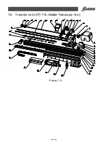
Страница 115: ...115 142 7 8 Traverse Unit ST1 T S Middle Telescopic Arm Picture 7 8 ...
Страница 119: ...119 142 7 9 Main Arm ST1 T S Middel Telescopic Arm Picture 7 9 ...
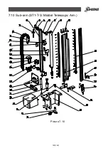
Страница 123: ...123 142 7 10 Sub arm ST1 T S Middel Telescopic Arm Picture 7 10 ...
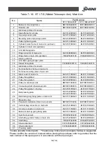
Страница 127: ...127 142 7 11 Crosswise Unit ST1 T S Middle Telescopic Arm Picture 7 11 ...
Страница 131: ...131 142 8 1 2 The Panasonic Servo Motor and Servo Driver Wiring Diagram Picture 8 2 ...
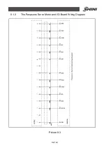
Страница 132: ...132 142 8 1 3 The Panasonic Servo Motor and I O Board Wiring Diagram Picture 8 3 ...
Страница 133: ...133 142 8 1 4 The Delta Servo Motor and Servo Driver Wiring Diagram Picture 8 4 ...
Страница 134: ...134 142 8 1 5 The Delta Servo Motor and I O Board Wiring Diagram Picture 8 5 ...
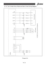
Страница 135: ...135 142 8 1 6 The Cuinsico Servo Motor and Servo Driver Wiring Diagram Picture 8 6 ...
Страница 136: ...136 142 8 1 7 The Cuinsico Servo Motor and I O Board Wiring Diagram Picture 8 7 ...
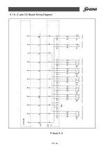
Страница 137: ...137 142 8 1 8 Z axis I O Board Wiring Diagram Picture 8 8 ...
Страница 138: ...138 142 8 1 9 Main Arm Wiring Diagram Picture 8 9 ...
Страница 139: ...139 142 8 1 10 Sub arm Wiring Diagram Picture 8 10 ...
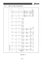
Страница 140: ...140 142 8 1 11 Main Arm Output Wirng Diagram Picture 8 11 ...
Страница 141: ...141 142 8 1 12 Signals Input Wiring Diagram Picture 8 12 ...
Страница 142: ...142 142 8 1 13 Signals Output Wiring Diagram Picture 8 13 ...