


124(142)
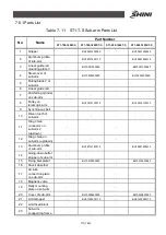
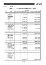
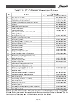
7.10.1
Parts List
Table 7- 17
:
ST1-T-S (Middel Telescopic Arm) Sub-arm
Part Number
No.
Name
ST1-1100-1800T
ST1-1100-1800DT
ST1-1300-2000T
ST1-1300-2000T
1
Sub-arm mounit plate
-
BH13000303010
-
BH13000303010
2
Fixing plate of
proximity switch
-
BL72001120020
-
BL72001120020
3
Cylinder (up/down)
holder frame on
sub-arm
-
BL72100800040
-
BL72100800040
4
Gripper
-
BH70401200040
-
BH70401200040
5
Aluminum profile of
sub-arm
-
BH78180020010
-
BH78180020010
6
Stack sensor sheet
-
BL72110500020
-
BL72110500020
7
Sensor fixing plate
-
YW09601400110
-
YW09601400110
8
Connection aluminum
profile of sub-arm
-
BH78180100040
-
-
9
Linear guide rail
-
YW31008202000
-
-
10
Pulley tightening plate
-
BL72113000020
-
BL72113000020
11
Cylinder (up/down) on
sub-arm
-
YE31405750000
-
-
12
Pulley fixing plate 2
-
BL72110600020
-
BL72110600020
13
Connecting shaft of
telescopic arm
-
BH78010900010
-
BH78010900010
14
Pulley on telescopic
arm
-
BH78011000010
-
BH78011000010
15
Pulley fixing plate 1
-
BL72301700020
-
BL72301700020
16
Synchronous belt
-
YR00052000200
-
YR00052000200
17
Pulley fixing plate 3
-
BL72300500040
-
BL72300500040
18
Drag (up/down) on
sub-arm
-
YE60250005500
-
YE60250005500
19
Drag (up/down)
connector on sub-arm
-
BL72000900020
-
BL72000900020
20
Belt down-going fixing
plate on sub-arm
-
-
-
-
21
Belt pressing plate
-
BL72122000040
-
BL72122000040
22
Arm down-going baffer
-
BL72001100040
-
BL72001100040
23
Cylinder fixing plate
-
BH91451600110
-
BH91451600110
24
Terminal mounting
plate on sub-arm
-
-
-
-
25
Terminal bottom frame
on sub-arm
-
-
-
-
26
Belt up-going fixing
plate on sub-arm
-
BL72100400020
-
BL72100400020
27
Magnetic valve
-
-
-
-
28
Penmatic distribution
block on sub-arm
-
BH70258300040
-
BH70258300040
Содержание ST1-S
Страница 1: ...ST1 S User Manual Date May 2016 Vision V1 0 English ...
Страница 2: ......
Страница 10: ...10 142 ...
Страница 41: ...41 142 4 Operating Instruction 4 1 Hand Controller 4 1 1Operation Pannel of Hand Controller Picture 4 1 ...
Страница 94: ...94 142 7 Assembly Diagram 7 1 Traverse Unit ST1 S and ST1 T S Picture 7 1 ...
Страница 99: ...99 142 7 2 Vertical Unit ST1 S Picture 7 2 ...
Страница 102: ...102 142 7 3 Main Arm Unit ST1 S Picture 7 3 ...
Страница 105: ...105 142 7 4 Sub arm Unit ST1 S Picture 7 4 ...
Страница 108: ...108 142 7 5 Main Arm ST1 T S Picture 7 5 ...
Страница 110: ...110 142 7 6 Sub arm ST1 T S Picture 7 6 ...
Страница 113: ...113 142 7 7 Vertical ST1 T S Picture 7 7 ...
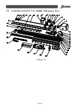
Страница 115: ...115 142 7 8 Traverse Unit ST1 T S Middle Telescopic Arm Picture 7 8 ...
Страница 119: ...119 142 7 9 Main Arm ST1 T S Middel Telescopic Arm Picture 7 9 ...
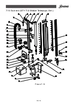
Страница 123: ...123 142 7 10 Sub arm ST1 T S Middel Telescopic Arm Picture 7 10 ...
Страница 127: ...127 142 7 11 Crosswise Unit ST1 T S Middle Telescopic Arm Picture 7 11 ...
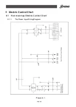
Страница 131: ...131 142 8 1 2 The Panasonic Servo Motor and Servo Driver Wiring Diagram Picture 8 2 ...
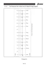
Страница 132: ...132 142 8 1 3 The Panasonic Servo Motor and I O Board Wiring Diagram Picture 8 3 ...
Страница 133: ...133 142 8 1 4 The Delta Servo Motor and Servo Driver Wiring Diagram Picture 8 4 ...
Страница 134: ...134 142 8 1 5 The Delta Servo Motor and I O Board Wiring Diagram Picture 8 5 ...
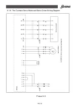
Страница 135: ...135 142 8 1 6 The Cuinsico Servo Motor and Servo Driver Wiring Diagram Picture 8 6 ...
Страница 136: ...136 142 8 1 7 The Cuinsico Servo Motor and I O Board Wiring Diagram Picture 8 7 ...
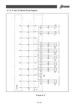
Страница 137: ...137 142 8 1 8 Z axis I O Board Wiring Diagram Picture 8 8 ...
Страница 138: ...138 142 8 1 9 Main Arm Wiring Diagram Picture 8 9 ...
Страница 139: ...139 142 8 1 10 Sub arm Wiring Diagram Picture 8 10 ...
Страница 140: ...140 142 8 1 11 Main Arm Output Wirng Diagram Picture 8 11 ...
Страница 141: ...141 142 8 1 12 Signals Input Wiring Diagram Picture 8 12 ...
Страница 142: ...142 142 8 1 13 Signals Output Wiring Diagram Picture 8 13 ...