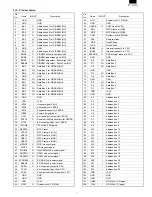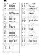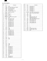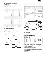
CHAPTER 7. TCP/IP I/F PWB DESCRIPTION
1. GENERAL DESCRIPTION
This control board is an Ethernet board that supports the TCP/IP
protocol.
2. BLOCK DIAGRAM
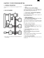
When writing data into FLASH, switch /CS0to EP-ROM and /CS3
to FLASH Memory.
3. CONFIGURATION
CPU :
[HitachiSH-2 Series SH7014 (20MHz)]
As external memory spaces, CS0 - CS3 and DRAM space are pro-
vided. This board assigns FLASH Memory to CS0, SRAM to CS1,
dual-port SRAM to CS2, and LAN controller to CS3.
LAN Controller : [RealtekRTL8019AS(20MHz)]
LAN controller is assigned to CS space.
Because of pseudo ISA connection, each register is assigned to ad-
dresses of H00C00300 and after.
ROM(FLASH Memory) :
[SharpLH28F004BVT(4Mbits)]
<Access Time = 90ns>
ROM (FLASH Memory) is assigned to CS0 space.
Data is written onto FLASH Memory from UV-EPROM by switching
the CSO space to UV-EPROM and the CS3 space to FALSH Mem-
ory.
MAC Address is written on FLASH Memory.
•
Company code is assigned to "08001FH".
•
The serial number and adjustment byte are stored in an area of 4
bytes from the address H’0007C000.
<The serial number is acquired according to Sharp’s in-house
specification(SS).>
RAM : [S-RAM 1Mbits]
<Access Time=70ns>
Assigned to CS1 space.
[IDT Dual-Port SRAM IDT7134]<Access Time=55ns>
Assigned to CS2 space.
The IDT7134 does not have any LOGICiBusy or Semaphorej, access
to the same address from both sides is inhibited.
Pulse Trans : [Pulse78Z034]
It is used for the 10Base-T standard and has a choke coil built in at
the output side.
Dual-Port
RAM
4k byte
CN
RJ-45
Data Bus
Address Bus
Da
ta
Bus
LOGIC
/CS1
/CS2
/INTHR
/INTHW
/INTSR
/INTSW
10MHz
/CS0
/CS0
/CS3
/CS3
/CS2
/CS1
/CS0
/HWACK
/HRACK
/SWRQ
/SRRQ
CPU
(SH-2)
/DPCS,
/WR,/RD
Address
Bus
LD0~LD7
LA0~LA11
FLASH
512k byte
LD0~LD7
LA0~LA18
LD0~LD7
LA0~LA18
SRAM
128k byte
LD0~LD7
LA0~LA19
LD0~LD7
LA0~LA18
LAN Cnt.
(8bit-Bus)
EP-ROM
(Writing in
to FLASH)
512k byte
Содержание UP-600
Страница 8: ......
Страница 77: ...CHAPTER 9 PWB LAYOUT 1 MAIN PWB 1 A side R VRD RC2EY103J is added IC1 94pin R71 ...
Страница 78: ...2 B side Symbol PartsCod ...
Страница 79: ...2 CKDC PWB 3 DISPLY MCR PWB 1 A side 2 B side 4 RS232 RELAY PWB 1 A side 2 B side ...
Страница 80: ...5 IPL ROM PWB 1 A side 8 POP UP DISPLY 9 LCD I F PWB 2 B side 6 TCP IP RELAY PWB 7 VR PWB ...
Страница 81: ...10 TCP IP I F PWB B side A side ...


