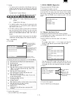
4)-3. CH2 Check
Checking
The procedure for checking, display and the method of exiting the
programs are the same as for the CH1 check.
4)-4. CH3 Check
Checking
The procedure for checking, display and the method of exiting the
program are the same as for the CH1 check.
4)-5. CH4 Check
Checking
The procedure for checking, display and the method of exiting the
program are the same as for the CH1 check.
4)-6. CH5 Check
Checking
The procedure for checking, display and the mothod of exiting the
programs are the same as for the CH1 check.
4)-7. CH6 Check
Checking
The procedure for checking, display and the method of exiting the
programs are the same as for the CH1 check.
4)-8. CH7 Check
Checking
The procedure for checking, display and the method of exiting the
programs are the same as for the CH1 check.
4)-9. CH8 Check
For checking CH8, the following loop-back connector is used.
Checking
The following checks are performed.
i. Control signal check
ER8
RS8
DR8
Ci8
CD8
CS8
OFF
OFF
OFF
OFF
OFF
OFF
OFF
ON
OFF
ON
ON
OFF
ON
OFF
ON
ON
ON
ON
The program performs the read checks of the above inputs.
During the read check, ER and RS are changed over in the above
order, checking the logic of DR, CI, CD and CS.
If the logic is different from those listed in the table, the error
message appears.
PATTERN 1
ER8
RS8
CI8
CD8
OFF
ON
OFF
OFF
ON
OFF
OFF
OFF
ON
ON
OFF
OFF
"No Connect" is displayed on the next line of PASS!!.
PATTERN 2
ER8
RS8
CI8
CD8
OFF
ON
OFF
OFF
ON
OFF
ON
OFF
ON
ON
ON
OFF
"CI Connect is displayed on the next line of PASS!!
PATTERN 3
ER8
RS8
CI8
CD8
OFF
ON
OFF
OFF
ON
OFF
OFF
ON
ON
ON
OFF
ON
"CD Connect! is displayed on the next line of PASS!!
If the logic is different from those in PATTERN 1 - 3, the error
message appears.
"ON" means active low and "OFF" active high.
The above checks are repeated for four cycles.
ii. Data transfer check
As check data, loop back data transfer of 256 bytes of 00H - 0FFH
is performed, the baud rate is set for115200 bps.
Display
Details of the errors are printed on the journal.
ERROR
No.
ERROR print
Details of ERROR
1
ER-DR : ERROR
ER-DR LOOP ERROR
2
ER-CI : ERROR
ER-CI LOOP ERROR
3
RS-CD : ERROR
RS-CD LOOP ERROR
4
RS-CS : ERROR
RS-CS LOOP ERROR
5
6
7
8
TXEMP : ERROR
TXEMP is not set.
9
TXEMP INT : ERROR
TXEMP interrupt does not
occur.
10
TXRDY : ERROR
TXRDY is not set.
11
TXRDY INT : ERROR
TXRDY interrupt does not
occur.
1pin
RS
2pin
ER
3pin
SD
4pin
CI/CD
5pin
GND
6pin
RD
7pin
DR
8pin
CS
PASS!!(or ERROR!!)
RS232 CH8 Check
CD Connect(or CI
Connect, No Connect
)
Содержание UP-600
Страница 8: ......
Страница 77: ...CHAPTER 9 PWB LAYOUT 1 MAIN PWB 1 A side R VRD RC2EY103J is added IC1 94pin R71 ...
Страница 78: ...2 B side Symbol PartsCod ...
Страница 79: ...2 CKDC PWB 3 DISPLY MCR PWB 1 A side 2 B side 4 RS232 RELAY PWB 1 A side 2 B side ...
Страница 80: ...5 IPL ROM PWB 1 A side 8 POP UP DISPLY 9 LCD I F PWB 2 B side 6 TCP IP RELAY PWB 7 VR PWB ...
Страница 81: ...10 TCP IP I F PWB B side A side ...


