6)-5. Data Transmission Check
The program performs a data transfer test using an actual estab-
lished system.
The system consists of 1 master machine and up to 63 satellite
machines.
Cautions to be taken when starting the test.
•
If this test is performed on the ECRs set for LAN, cancel the
settings before starting the test.
•
If this test is performed using an established system, disconnect
the LAN cables from the ECRs you do not want to test or cancel
their LAN settings. If the test is performed with those ECRs set for
LAN, their data might be destroyed.
•
After canceling the LAN settings of all ECRs on the system, set
them for the data transfer test.
Set the satellite machines first, and then set the master machine.
•
The Diag of the UP-600 uses a private IP address. Each IP ad-
dress is unique on the Internet. When building a private network,
you should be careful not to allow your internal packet used for
your own network to leak to the Internet, because it might cause
confusion. The Internet Assigned Numbers Authority (IANA) speci-
fies IP addresses that can be used without registration. These
addresses can only be used within a private network and are not
route controlled between sites of the Internet.
Class A : 10.x.x.x
Class B : 172.16.x.x 172.31.x.x
Class C : 192.168.0.x?192.168.255.x
It is strongly recommended to use addresses within the above
range when building a private network.
In this Diag. program, the following private IP addresses are as-
signed to the terminal Nos. (1 - 64).
TERMINAL NO.1 =
192.168.0.1
TERMINAL NO.2 =
192.168.0.2
......
TERMINAL NO.31 = 192.168.0.63
TERMINAL NO.32 = 192.168.0.64
Setting
i. Setting satellite machines.
On the menu screen, select DATA Trans. (SA). The screen is
shown below.
Enter the terminal No. of the machine you are going to test (a
2-digit number from 1 - 32) + Enter. The screen looks like this:
i. Setting the master machine.
On the menu screen, select DATA Trans. (MA). The screen
looks like this:
Enter the terminal No. of the machine you want to test (a
2-digit number from 1 - 64)+ Enter. The screen looks like this:
Enter the terminal No. (a 2-digit number from 1 -64) of the
satellite machines which are connected to the test m
Enter. The screen looks like this:
When performing the test with multiple satellite machines, type their
terminal numbers (2-digit numbers within the range from 1~64) and
press Enter. In addition, you specify the satellite machines using the
area specification function without typing terminal numbers. This is
achieved by typing the first terminal number (2 digits) and the last
terminal number (2 digits) of the satellite machines and then press
Enter. For example, if you want to specify the terminal numbers of
satellite machines from 5 to 15, type "0515" for T-No. and press Enter.
When executing, press the Enter key without typing the terminal
numbers.
The display appears like this:
Note that the terminal numbers of the master machine and satel-
lite machines should not be the same. When the terminal numbers
are to be specified using the area specification function, any termi-
nal number that is used for the master machine will be excluded
from the specification of satellite machine terminal numbers.
With the above setting, data transfer is performed between the
master machine and the satellite machines.
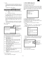
INPUT SA T-NO.
DATA Trans.(SA)
Enter a number
within the range
from 1 64.
DATA SEQ.NO. : 0000
INPUT SA T-NO. : XX
DATA Trans.(SA)
The terminal No. you
entered is displayed.
INPUT MA T-NO. :
DATA Trans.(MA)
Enter a number
within a range
from 1~64.
INPUT MA T-NO. : XX
DATA Trans.(MA)
INPUT SA T-NO. :
The terminal No. you
entered is displayed.
INPUT MA T-NO. : XX
DATA Trans.(MA)
INPUT SA T-NO. : XX( or XXXX)
The terminal No. of
the master machine
you entered is
displayed.
The terminal No. of
the satellite machine
you entered is
displayed.
INPUT MA T-NO. : XX
DATA SEQ.NO. : 0000
The terminal No. of
the master machine
you entered is
displayed.
Содержание UP-600
Страница 8: ......
Страница 77: ...CHAPTER 9 PWB LAYOUT 1 MAIN PWB 1 A side R VRD RC2EY103J is added IC1 94pin R71 ...
Страница 78: ...2 B side Symbol PartsCod ...
Страница 79: ...2 CKDC PWB 3 DISPLY MCR PWB 1 A side 2 B side 4 RS232 RELAY PWB 1 A side 2 B side ...
Страница 80: ...5 IPL ROM PWB 1 A side 8 POP UP DISPLY 9 LCD I F PWB 2 B side 6 TCP IP RELAY PWB 7 VR PWB ...
Страница 81: ...10 TCP IP I F PWB B side A side ...


