59
Selectronic Australia
Rev 41 - Dec 2022
Service
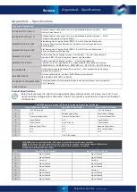
Disconnection and Isolation
Disconnection and isolation of SP PRO
The SP PRO must have external disconnect devices installed on AC Output (AC Load), AC Source and Battery port.
To disconnect and isolate the inverter, all disconnect devices on all three ports must be in the OFF position
(disconnected)
Inverter Demand Response Modes (DRM)
Demand Response modes available
DRM0 to DRM8 available. To enable configure DRM Mode using SP LINK, see SP LINK Manual for more details
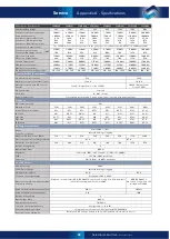
Suitable Battery Types and Voltage
Decisive voltage class of battery port
A
C
Over voltage class of battery port
OVC II
OVC II
Over current protection rating
(Required to be installed external to
inverter)
250A
250A
125A
160A
250A
160A
250A
250A
Lead acid batteries – Nominal Voltage
24V
24V
48V
48V
48V
120V
120V
120V
Lead Acid battery type
Suitable for all types of Lead acid battery technologies in both sealed and flooded cells. SP PRO charger settings
must be configured to suit battery manufacturer’s specifications
Lithium battery – Nominal voltage and
number of cells (assuming 3.2V per cell)
25.6V
8 cells
25.6V
8 cells
51.2V
16 cells
51.2V
16 cells
51.2V
16 cells
128V
40 cells
128V
40 cells
128V
40 cells
Lithium battery type. No
communications with BMS
Any Lithium battery technology is suitable provided it is approved for the intended application. The Lithium battery
bank must have its own Battery Management System that provides full protection and disconnection functions to
ensure safe operation of the battery bank at all times and under all conditions.
SP PRO charger settings must be configured to suit battery manufacturer’s specifications
Lithium battery type. With
communications between SP PRO and
BMS .
Compatible with a number of Lithium battery brands with communications between the SP PRO and the battery
BMS. Please see the Selectronic web site for the list of approved batteries
Flow Battery – Nominal voltage
24V
24V
48V
48V
48V
120V
120V
120V
Flow battery type
Any Flow battery technology is suitable provided it is approved for the intended application. SP PRO charger
settings must be configured to suit battery manufacturer’s specifications.
Use the Custom Battery setting within the SP PRO
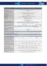
SP Pro Series Specifications
SPMC240
SPMC241
SPMC480
SPMC481
SPMC482
SPMC1201
SPLC1200
SPLC1202
Features
Powerchain
Included. Connect multiple SP PROs into one single-phase or multi-phase system. Up to four SP PROs per phase.
(Up to twelve SP PROs in a three-phase system)
Battery temperature sensor
Included
Mid point battery voltage sensing
Included
Front panel display and controls
22 x LED indicators with auto brightness for charger status, battery capacity, alarms, AC status.
Generator control button. On button. Silence Alarm button
Digital Inputs
4 of Max 60V DC ( Active > +10V, Inactive < +3V )
Inverter Topology
Isolated
Protective Class
Class 1 (AC Source, AC Load and battery ports)
Operating ambient temperature
-10C to 60C
Shunt Inputs
2 of + / -100mV, adjustable 25mV to 100mV, 25A to 1,000A
Analogue Inputs
2 general purpose logged 0-60V
n / a
Relay Outputs
4 of 60V, 500mA rated dry contacts
Digital Outputs
3 of 60V, 5mA rated Open collector
Communication ports
USB and RS232 for SP LINK communications (optional remote comms via Select.live) RS485 for Managed AC Solar
and Managed batteries
CAN – Managed battery systems
SYNC – Powerchain inter inverter communications
Memory retention of settings & data
Permanent
Select.live monitoring option.
Option allows remote monitoring of system parameters and SP LINK remote connection
SP LINK configuration and monitoring
software
Standard, for SP PRO display, configuration of parameters, system monitoring and diagnostics.
Remote connection possible via Select.live option.
Dimensions (mounted) W x H x D
375 x 690 x 220
540 x 870
x 293
540 x 870
x 293
Weight (with wall mount)
35kg
39kg
35kg
40kg
42kg
42kg
113kg
115kg
Standards
IEC62019.1, IEC62019.2, IEC 62040-1:2017 / AS 62040.1:2019, IEC 62477-1:2012
AS/NZS 61000-6-3:2007
AS/NZS 61000-6-4:2007
Grid Connect AS/NZS 4777.2:2020
appendix M, Stand Alone Inverter
requirements
No
No
Yes
Yes
Yes
No
Yes
Yes
Grid Protection
IEC 62116:2014
Protection
IP43
Appendix A - Specifications
Содержание SPPRO 2i Series
Страница 1: ......
Страница 2: ...Selectronic Australia 2023 ...
Страница 51: ...47 Selectronic Australia Rev 41 Dec 2022 Operation SP PRO Operation ...
Страница 64: ...Contents Doc O10003 Part 004122 Rev 41 Dec 2022 ...


