19
Selectronic Australia
Rev 41 - Dec 2022
Installation
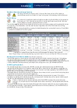
Multiple Hazardous Energy Sources
AC wiring is fed from multiple sources. Care must be taken to ensure that under no
circumstances could a user access or touch wiring, even after opening all circuit breakers.
Earth Wiring
It is critical that all protective Earth connections made within the SP PRO use the protective
Earth terminal. This is the Earth terminal that is on the right-hand side of the AC terminals
and marked with an Earth symbol enclosed in a circle.
The inverter
must
be earthed to the installation’s Earth system. A minimum copper earthing conductor no less
than the size in the table below, must be used. See local regulations for further information on earthing
conductor size.
Earth the inverter by connecting Earth wiring from the Switchboard to the inverter Earth terminal. The SP PRO
is suitable for multiple Earth neutral systems.
Cable and CB sizing for AC wiring – SP PRO
SPMC240 SPMC241
SPMC480
SPMC481
SPMC482 SPMC1201 SPLC1200
SPLC1202
Maximum
AC CB rating
63A 6kA
C curve
1
63A 6kA
C curve
1
63A 6kA
C curve
1
63A 6kA
C curve
1
63A 6kA
C curve
1
63A 6kA
C curve
1
125A 10kA
C curve
1
AC terminal size
35mm
2
35mm
2
35mm
2
35mm
2
35mm
2
35mm
2
50mm
2
Strip length for AC
terminals A and N
18mm
18mm
18mm
18mm
18mm
18mm
18mm
Strip length for
Earth terminal
12mm
12mm
12mm
12mm
12mm
12mm
16mm
Minimum Earth
cable size
6mm
2
6mm
2
6mm
2
6mm
2
6mm
2
6mm
2
16mm
2
Terminal torque
settings
3.2-3.7Nm
3.2-3.7Nm
3.2-3.7Nm
3.2-3.7Nm
3.2-3.7Nm
3.2-3.7Nm
6.0-8.0Nm
Table given as a reference only. Please ensure all wiring complies with relevant safety standards.
Note 1: If high starting currents are expected (e.g. large motor loads), a D curve circuit breaker (CB) may be required
Residual Current Device (RCD)
Type Recommendation
The SP PRO produces a low distortion sine wave output via 50 / 60Hz isolation transformer. This topology
ensures that the output is sinusoidal and that there is no DC component associated with the SP PRO AC
supply. Standard type AC RCDs are suitable for use with an SP PRO. Other types of RCDs may also be used. A
suitably rated RCD should be chosen according to local wiring rules and as per AS/NZS 3000:2018.
AC Wiring Preparation
The intended application and use of the SP PRO must be well understood to allow the SP PRO to be
appropriately connected to the installation. How the SP PRO is wired into the Switchboard is dependent on
whether all the installation’s site loads or only essential site loads are to be supplied by the SP PRO for tariff
optimisation, self consumption or battery backup.
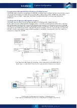
The below diagram shows AC wiring only and indicates the customer circuits, some of which are battery back-
up protected, and some of which are grid supply only.
Attention must be paid to the neutral conductor and connection through to the site loads. The neutral
conductor connecting to the site loads must be maintained such that operation of the inverter isolator would
not alter the bonding between neutral and Earth.
There is a terminal link for neutral continuity within the SP PRO, between the Load and source
terminals. This neutral link must be retained where neutral continuity is not provided external to the
SP PRO.
The neutral conductor must remain connected through to the site loads and particular care should be taken
with the placement of RCDs. These devices open both active and neutral conductors, thus the SP PRO must
be installed on the grid side of these devices.
Cabling and Fusing
Содержание SPPRO 2i Series
Страница 1: ......
Страница 2: ...Selectronic Australia 2023 ...
Страница 51: ...47 Selectronic Australia Rev 41 Dec 2022 Operation SP PRO Operation ...
Страница 64: ...Contents Doc O10003 Part 004122 Rev 41 Dec 2022 ...

