35
Selectronic Australia
Rev 41 - Dec 2022
Installation
Commissioning
Introduction
Now that the system has been installed and the SP PRO has been configured, it is vital that the following
commissioning processes be followed to verify correct installation of the system. Spending this time now will
save time later.
It is important that all the details are filled out in the relevant commissioning sheets below. This will assist in
diagnosing any system errors now and in the future.
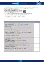
To ensure that you receive the highest level of support, please ensure that the following commissioning
documents are completed and available before contacting Selectronic Support.
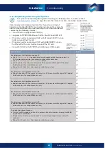
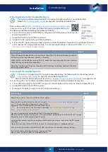
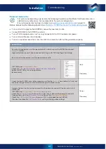
Please check off or record the value of all items in the following checklist. For single-phase systems just
record the value for L1 (ignore L2 and L3).
Diagnostics During Commissioning
If the alarm buzzer sounds and one of the alarm LEDs is red during the commissioning process, please do the
following to diagnose the system fault:
•
Connect to the SP PRO or the System Manager (in Powerchain) via a Windows computer that is running
SP LINK.
•
To read messages in the Attention Required field, go to >
Data View
>
Now
>
Attention Required
•
Right click the
Attention Required
heading to view the SP LINK Manual, which lists all the messages, their
meanings and any required actions.
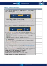
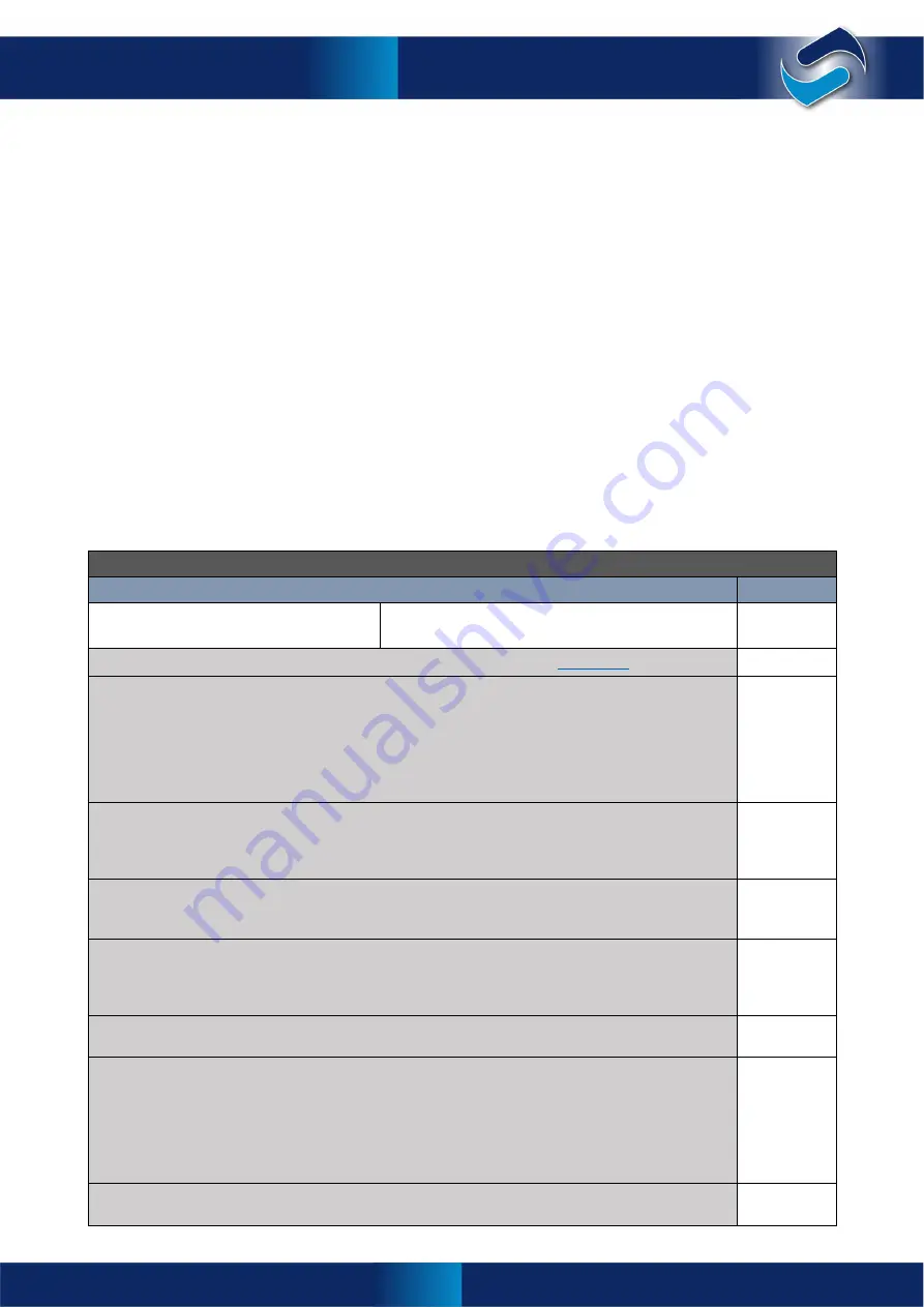
Common System Checks
Standard checks that are common to all SP PRO based power systems
Item to check
Result
Record Inverter model numbers and serial
numbers:
Model:
Serial:
Check the physical location of the SP PRO(s) in relation to all items listed in
on page 8
Check all main battery connections are correct and tight and that insulation is not clamped in the
terminal. Checks include the following:
•
Battery interconnects
•
Battery connections to battery
•
Connections to battery fuses or CBs
•
Connection to intermediate terminals
•
Connection to the SP PRO(s)
Check polarity of all main battery connections, including:
•
At the battery bank
•
At the fuse or CB connections. Check that they are not crossed
•
At the SP PRO(s) battery terminals
Check pre-charge / Battery Sense wiring, including:
•
Connections to the battery bank
•
Connection to the SP PRO(s). Check insulation is not clamped in terminal
Check polarity of pre-charge / Battery Sense wiring, including:
•
At the battery bank
•
At the fuse or CB connections. Check that they are not crossed
•
At the SP PRO(s) battery terminals
With a multi-meter, check the voltage on the mid-point terminal (where installed) on the pre-charge /
Battery Sense. This should be half the battery bank voltage.
Check all AC wiring connected to the SP PRO(s), including the following:
•
The AC Source terminals are wired to the grid or generator supply
•
The AC Load terminals are wired to the customer’s site loads
•
The AC outputs of the connected Selectronic Certified solar inverters are connected to the AC
Load terminals on the SP PRO(s)
•
All Neutral and Line connections are correct polarity
•
The Protective Earth terminal is connected
Retighten all AC wiring terminals, N, L and E, and check there is no insulation in terminal, including
connections to the SP PRO(s)
Commissioning
Содержание SPPRO 2i Series
Страница 1: ......
Страница 2: ...Selectronic Australia 2023 ...
Страница 51: ...47 Selectronic Australia Rev 41 Dec 2022 Operation SP PRO Operation ...
Страница 64: ...Contents Doc O10003 Part 004122 Rev 41 Dec 2022 ...


