10.9
Date Code 20100129
Instruction Manual
SEL-751A Relay
Testing and Troubleshooting
Commissioning Tests
Arc-Flash Protection
Tests
Follow the procedures described in
to complete the
installation of the Arc-Flash Detection (AFD) fiber-optic sensors in the
switchgear equipment to be protected. Make sure the switchgear doors,
panels, etc., are closed and in the final operating configuration. This will
assure that the ambient light as measured by the sensors is indicative of the
normal operating condition. DO NOT ENERGIZE the switchgear for the
commissioning tests described below. The relay must have the application
settings as required, be energized, and in the ENABLED state.
Arc-Flash Detection (AFD) System Continuous Self-Testing
The SEL-751A relay continuously tests (periodic) and monitors all four arc-
flash sensor subsystems and reports the status. The test period is constant, set
to 10 minutes.
1. Point-Sensor AFD Self-Test
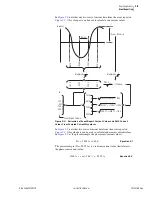
Each point-sensor AFD subsystem on the relay has a Transmit
LED channel and a Light Detector channel. The LED
periodically sends a light pulse through the transmit fiber cable,
which is "coupled" into the receive fiber cable in the point
sensor. The light travels back to the light detector on the relay.
The light measurement by the detector is used to determine the
integrity of the point-sensor AFD loop and report PASS/FAIL
status.
2. Bare-Fiber Sensor AFD Self-Test
The bare-fiber sensor is basically a loop, starting from the
Transmit LED and returning to the Light Detector. The relay
self-test involves sending a light pulse around the loop and
measuring the light received at the detector. The light
measurement by the detector is used to determine the integrity
of the Bare-Fiber Sensor AFD loop and report PASS/FAIL
status.
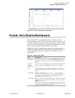
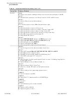
METER LIGHT Report
Use the serial port ASCII command
METER
L
and view the METER LIGHT
report as shown in
.
The report shows the light intensity measurements in percent of full scale (%)
for the four AFD channels. This measurement represents the "background" or
the "ambient" light in the switchgear areas being monitored for arc-flash. This
measurement is used in determining the "Time-Over Light" TOL1 to TOL4
settings for arc-flash protection (refer to
Section 4: Protection and Logic
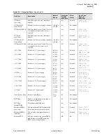
for details). If there is excessive background light (any of the relay
word bits AFSnEL picks up) or if there is a diagnostic failure (any of the relay
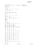
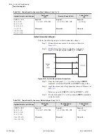
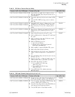
PHROT := ACB
Ia = 2.5
∠−
26
Ib = 2.5
∠
+94
Ic = 2.5
∠−
146
Expected:
P = 0.4677 • CTR • PTR
Expected:
Q = 0.2286 • CTR • PTR
Expected:
pf = 0.90 lag
Vab = 120
∠−
30
Vbc = 120
∠+
90
Measured:
Measured:
Measured:
Table 10.5
Power Quantity Accuracy—Delta Voltages
(Sheet 2 of 2)
Applied Currents and Voltages
Real Power
(kW)
Reactive Power
(kVAR)
Power Factor
(pf)
Содержание 751A
Страница 1: ...20100129 SEL 751A Feeder Protection Relay Instruction Manual PM751A 01 NB...
Страница 6: ...This page intentionally left blank...
Страница 12: ...This page intentionally left blank...
Страница 18: ...This page intentionally left blank...
Страница 26: ...This page intentionally left blank...
Страница 92: ...This page intentionally left blank...
Страница 218: ...This page intentionally left blank...
Страница 250: ...This page intentionally left blank...
Страница 376: ...This page intentionally left blank...
Страница 392: ...This page intentionally left blank...
Страница 408: ...This page intentionally left blank...
Страница 418: ...This page intentionally left blank...
Страница 434: ...This page intentionally left blank...
Страница 462: ...This page intentionally left blank...
Страница 544: ...This page intentionally left blank...
Страница 580: ...This page intentionally left blank...
Страница 584: ...This page intentionally left blank...
Страница 632: ...This page intentionally left blank...
Страница 636: ...This page intentionally left blank...
Страница 640: ...This page intentionally left blank...

