


4.40
SEL-751A Relay
Instruction Manual
Date Code 20100129
Protection and Logic Functions
Voltage-Based Protection
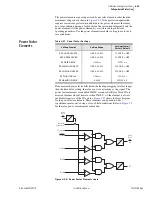
Angle Difference Example (Voltages VP and VS are “Slipping”).
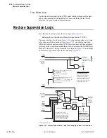
Refer to
. For example, if the breaker close time is 100 ms, set
TCLOSD := 100. Presume the slip frequency is the example slip frequency
calculated previously. The Angle Difference Calculator calculates the angle
difference between voltages VP and VS, compensated with the breaker close
time:
Angle Difference = |(
∠
VP –
∠
VS) + [(fP – fS) • TCLOSD • (1 / 1000) •
(360°/slip cycle)]|
Intermediate calculations:
(fP – fS) = (59.95 Hz – 60.05 Hz) = –0.10 Hz = –0.10 slip cycles/second
TCLOSD • (1 / 1000) = 0.1 second
Resulting in:
Angle Difference
= |(
∠
VP –
∠
VS) + [(fP – fS) • TCLOSD • (1 / 1000) • (360°/slip cycle)]|
= |(
∠
VP –
∠
VS) + [–0.10 • 0.1 • 360°]|
= |(
∠
VP –
∠
VS) – 3.6°|
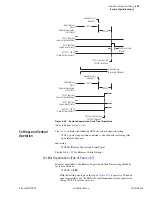
During the breaker close time (TCLOSD), the voltage angle difference
between voltages VP and VS changes by 3.6 degrees. This angle
compensation is applied to voltage VS, resulting in derived voltage VS*, as
shown in
.
The top of
shows the Angle Difference
decreasing
—VS* is
approaching VP. Ideally, circuit breaker closing is initiated when VS* is in
phase with VP (Angle Difference = 0 degrees). Then when the circuit breaker
main contacts finally close, VS is in phase with VP, minimizing system shock.
shows the Angle Difference
increasing
—VS* is
moving away from VP. Ideally, circuit breaker closing is initiated when VS* is
in phase with VP (Angle Difference = 0 degrees). Then when the circuit
breaker main contacts finally close, VS is in phase with VP. But in this case,
VS* has already moved past VP. In order to initiate circuit breaker closing
when VS* is in phase with VP (Angle Difference = 0 degrees), VS* has to slip
around another revolution, relative to VP.
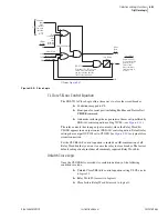
Synchronism-Check Element Outputs
Synchronism-check element outputs (Relay Word bits 25A1 and 25A2 in
) assert to logical 1 for the conditions explained in the following
text.
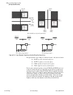
Voltages VP and VS Are “Static” or Setting TCLOSD = OFF.
To implement a
simple fixed-angle synchronism-check scheme, set TCLOSD := OFF and
25SF = 0.50. With these settings, the synchronism check is performed as
described in the top of
.
If there is the possibility of a high slip frequency, exercise caution if
synchronism-check elements 25A1 or 25A2 are used to close a circuit breaker.
A high slip frequency and a slow breaker close could result in closing the
breaker outside the synchronism-check window. Qualify the breaker close
command with a time delay, such as:
SV06 :=
25A1
CL :=
CC and SV06T
Set SV06PU with enough pickup delay to ensure that the slip frequency is low
enough for the circuit breaker to close within the synchronism-check window.
NOTE:
The angle compensation in
appears much greater
than 3.6 degrees.
is for
general illustrative purposes only.
Содержание 751A
Страница 1: ...20100129 SEL 751A Feeder Protection Relay Instruction Manual PM751A 01 NB...
Страница 6: ...This page intentionally left blank...
Страница 12: ...This page intentionally left blank...
Страница 18: ...This page intentionally left blank...
Страница 26: ...This page intentionally left blank...
Страница 92: ...This page intentionally left blank...
Страница 218: ...This page intentionally left blank...
Страница 250: ...This page intentionally left blank...
Страница 376: ...This page intentionally left blank...
Страница 392: ...This page intentionally left blank...
Страница 408: ...This page intentionally left blank...
Страница 418: ...This page intentionally left blank...
Страница 434: ...This page intentionally left blank...
Страница 462: ...This page intentionally left blank...
Страница 544: ...This page intentionally left blank...
Страница 580: ...This page intentionally left blank...
Страница 584: ...This page intentionally left blank...
Страница 632: ...This page intentionally left blank...
Страница 636: ...This page intentionally left blank...
Страница 640: ...This page intentionally left blank...


